Band hopping with the CG3000

I recently acquired a CG3000 Automatic Remote antenna tuner from Ebay that was advertised as being new, still in the box unused. I’m always very wary about purchasing stuff from Ebay as the site is full of scams and cheap Chinese rubbish these days.

I decided it would be handy to have an auto remote ATU to enable me to band hop quickly and easily without having to go outside and tinker so, I thought I’d put in a silly offer and see what happens.

Putting in an incredibly low offer I didn’t expect to hear anything however, the following day the offer was accepted! At this point I thought well it’s either a scam or someone just wants rid of it for one reason or another.

4 days after paying for the unit it arrived and sure enough, it was new still in it’s box and original wrapping, bargain!

Initially I used the CG3000 to make an NVIS antenna for inter-G contacts on the low bands. It worked extremely well and I’ve kept the 30m long end fed wire in place so that I can chat with other UK stations throughout the summer months.

Wanting to experiment further with the CG3000 I thought I’d look into getting onto the WARC bands as summer is coming and the higher bands normally come alive during the warmer months. Having the CG3000 remote tuner in the garden already I decided to see if I could make a vertical that would work on the higher frequencies. I started to look into what length of wire I should use with the tuner to get the best results across the bands and finally decided to go with 8.3m.

8.3m might seem a strange length to go with but, there is method to my madness!

8.3m is a half wave on the 17m band, this should be great for DXing as it will have a very low angle of radiation, around 5 degrees.

On the 15m band it will be roughly a meter longer than a half wave but, modelling shows it will still be good for working the DX.

On the 12m band it will be just under a 3/4 wave length, it will have a higher angle of radiation than on 17m and 15m but, it should still work well.

On the 30m band it will be just over a 1/4 wave length, this will also be good for DXing and will give me another band to play with.

Finally, on the 40m band it will be a little shorter than a quarter wave but, should still work fairly well and give me the ability to switch between the 5 bands in seconds.

I’m not worried about using it on the 20m or 10m band as these two are covered by my 20m EFHW vertical antenna that has already proven to be a superb DX antenna.

In the back of the shed I had a new 8.5m long telescopic fibreglass pole that would be ideal for getting the wire into the air. The CG3000 needs a relatively good ground connection and radials to tune against, fortunately I’d already sorted the ground out when I set the tuner up for the 30m long end fed NVIS antenna.

CG3000 Automatic Remote ATU connected to ground and antenna wire

Powering it up it tuned on all the bands I wanted and as a bonus it tuned the 80m band too. I doubt it will be particularly good on 80m as 8.3m of wire is rather short for such a low frequency but, could be OK for local ground-wave chatter.

So it was time to get on the air and see how it performed.

First up was 17m, the band was active which was good to hear and I set about working a few stations.

Stations worked on the 17m band using the CG3000 ATU and vertical antenna

Working into Japan was a breeze on 17m, I couldn’t believe it when I got through to JA4FKX first call. I also got into Thailand HS6OKJ first call too. I worked a few European and Russian stations and then started hunting for stations further afield. It wasn’t long before I’d worked PY7ZC and PY2IQ in Brazil, YV4GLF in Venezuala and a bunch of East Coast USA stations. As the sun headed west I worked VE7SA and VA7QI on the West Coast of Canada.

Tuning up on the 15m band I found the it was pretty dead however, I did manage to work VE1JBC which proved the antenna worked on 21Mhz but, needed more testing when the conditions are better.

Tuning up onto 12m was the same story, completely dead apart from one station calling CQ, LU8EX in Argentina! I gave a call back and got an immediate reply. We exchanged signal reports and then he was gone. More testing is also needed on this band but, getting into Argentina more than proves it’s a DX worthy antenna for the 12m band.

Tuning onto the 30m band I found a hive of activity and so set about working stations to see how the CG3000 and antenna combo worked on the lower frequencies. To my surprise it was extremely effective.
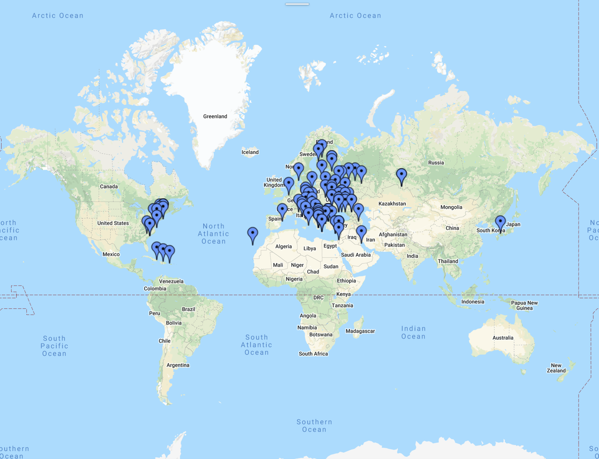
Stations worked on the 30m band using the CG3000 ATU and vertical antenna

As you can see on the map above, the slightly long 1/4 wave length antenna worked very well on the 30m band and I’ve been able to get contacts in Japan, Russia, most of Europe and into the East Coast USA and Caribbean. 8.3m of vertical wire makes an extremely good 30m band antenna!

I didn’t have a lot of time to check out the 40m band however, I did manage to work a few stations before I had to disappear. The CG3000 ATU tuned the 8.3m of wire up beautifully and I was surprised how many stations I could hear during the daylight hours.

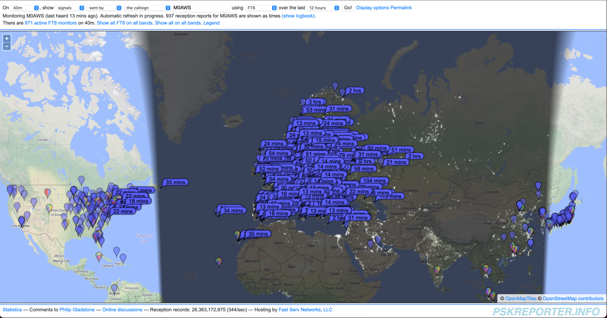
Stations worked on the 40m band using the CG3000 ATU and vertical antenna

I worked a few stations on 40m before closing down and heading off to do other, more important things. Considering it was still daylight I was impressed to get UI4P at just under 2000 miles. I clearly need to spend more time on the 40m band late into the night to see how well the antenna performs but, it looks promising!

So overall, the CG3000 remote auto tuner and 8.3m of wire give me exactly what I wanted, 17, 15m and 12m with the added bonus of 30m and 40m. DXing over the summer months will be a lot of fun for sure!

UPDATE: It works incredibly well on the 60m band too! I’ve just had to manage my first ever FT8 pileup on 60m including contacts into Canada, USA and Puerto Rico.

More soon …

Multi-band vertical tuned with CG3000 Remote Auto Tuner

160m Band NVIS Antenna Experiment

Following on from the 80m Band NVIS Antenna Experiment I spent some time using the same setup on the 160m band.

To recap, the NVIS antenna is a 30m long end-fed wire that is between 3 and 4m above the ground over it’s entire length. This is the longest wire I could get into my tiny U.K. garden and so I wanted to see what was really possible with such a low short wire on the low bands. My goal was to get good Inter-G signals so that I could chat with other U.K. and close European stations during the summer months. The tuning is done automatically by the CG3000 remote ATU I picked up very cheaply on Ebay.

Having very anti-antenna neighbours I have to tread carefully not to upset them as I have already rattled some cages having the 20m EFHW Vertical on an extending fibre glass pole at the end of the garden overlooking the farmers field.

The CG3000 remote ATU matches the 30m wire nicely on the 160m band with an SWR of less than 1.2:1 across the entire band with multiple retunes. It’s certainly very convenient to have such a setup.

Setting the power output on the radio to 25w which is the maximum I use for FT4/FT8 on the Yaesu FTDX10 I started WSJT-X and waited to see what I could hear. With the background noise swinging between S7-9 most of the time I was surprised at how many stations were being decoded. Some of the stations were barely visible on the waterfall but, I got consistent reliable decodes.

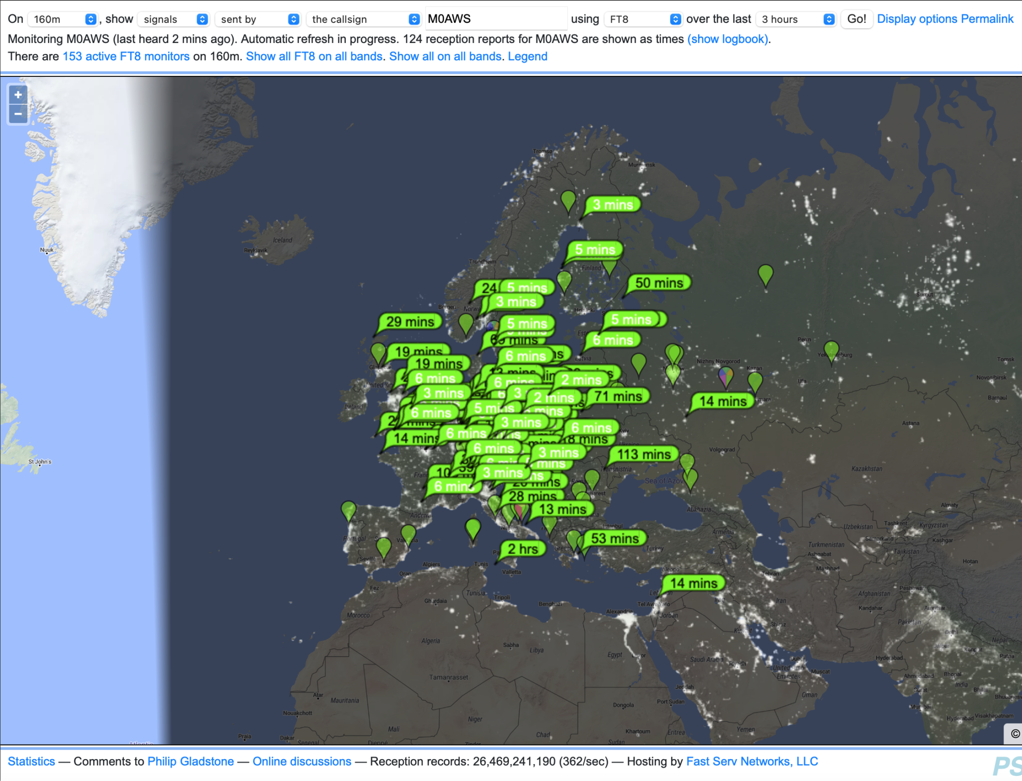
Stations heard during a 1 hour period on 160m NVIS Antenna Experiment

As you can see on the map above I was hearing stations from all over Europe and well into Russia. There certainly isn’t the proliferation of stations on the 160m band that there are on the 40m band but, there were enough for me to get some good results.

It was nice to reliably copy some U.K. stations on 160m FT8 even though I didn’t hear a single SSB station on the band.

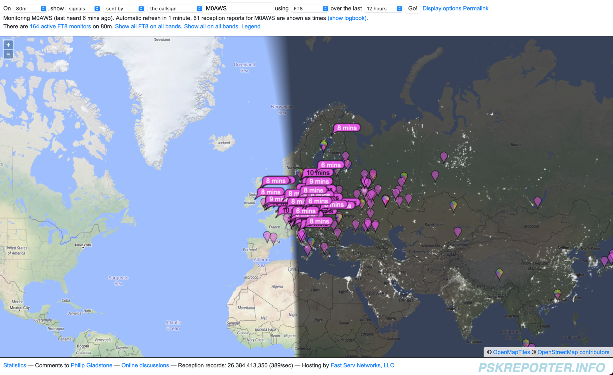
Map showing stations that heard M0AWS on 160m during the NVIS Antenna Experiment

Over a period of about 3.5 hours I was heard by a good number of European stations but, wasn’t able to work all that I heard as I was struggling to compete with the much more powerful stations. Limiting my transmit power to 25w to protect the PA on the radio does tend to limit my success at getting through to stations at times but, I am a firm believer in being able to hear better than I can shout, especially on the low bands.

Map showing all stations worked during the 160m NVIS Antenna Experiment

Over the test period I didn’t work a huge number of stations but, I did manage to work stations over a large area of Europe with the best distance being 1004 Miles into Finland, much further than I ever thought would be possible with such a simple setup.

I’m sure that when the band is in better shape with lower noise levels and better propagation the antenna will post probably perform better but, it’s certainly proved it can do the short hop NVIS comms that I was looking for.

I have designed a new NVIS antenna for the garden which manages to incorporate considerably more wire into the same space that is resonant on the 80m band. With the CG3000 remote ATU it should tune up well on 40m-160m and give much better results. This design does require a 10m fibre glass expending pole which I need to purchase before I can erect it in the garden. I’ll get all the information for the design onto the Antenna section of the website soon.

So to summarise, a 30m end-fed wire at between 3 and 4m above the ground will give good NVIS results on 40m-160m with a very low visual impact. For those like me that have a small garden, a simple antenna like this is much better than no antenna at all.

More soon …
80m Band NVIS Antenna Experiment

Following on from my 40m band NVIS antenna experiment I ran the same series of tests on the 80m band to see how well the NVIS antenna works.

Being only 30m long the antenna isn’t very well suited to the low bands but, with the tiny garden we have here in the U.K. and the anti-antenna neighbours it’s the best I can do.

I started off looking for SSB contacts only to find no one on the band. I eventually found G8MNY calling CQ from Croydon south of London. He was a huge 5/9+20db with me so I was hopeful that he’d hear me.

Tuning up the antenna on 3.710Mhz and setting the O/P to 40w I gave him a call and got an immediate response. We ended up chatting for around 30mins with ease, the band wasn’t too noisy and Jon was running 400w so he was a solid signal with me. My 40w got me a 5/8 report which I was very happy with.

Once we cleared I tuned around the band and even called CQ a few times, but there was nothing to be heard.

I went and had something to eat and then returned to the shack before the greyline, the band was a little more lively and so I switched over to FT8 mode and started working stations.

Stations initially heard on FT8 whilst still in daylight

I was really quite surprised how many stations I could hear and make contact with even though I was still in daylight. The effect of the greyline really is quite pronounced.

Stations that heard me on FT8 whilst still in daylight

I was being heard by a good number of continental stations even though I was still in daylight. Signal strengths were good and I was soon working stations one after another with ease.

As the night drew closer and the U.K. moved into darkness stations further east started appearing on the WSJT-X window and I was surprised how many I was able to work considering how low and short the antenna is for this band.

German stations were always the strongest throughout the test which is to be expected with an NVIS antenna as they are just across the north sea as the crow flies.

Map showing all stations heard on FT8 during 80m NVIS antenna experiment

By the end of the evening I’d heard a good number of stations with the most distant being north of the Kazakhstan/Mongolian border as shown on the map above.

All stations that heard M0AWS on FT8 throughout the NVIS antenna experiment

I was pleasantly surprised at how many stations were hearing me throughout the test, getting as far south as the islands off the coast of north Africa and well into Russia was amazing for a horizontal antenna that is only 4m-5m above the ground.

Map of all stations worked during the 80m NVIS antenna experiment

The number of contacts was nowhere near as prolific as during the 40m experiment mainly due to the fact that the band wasn’t as busy however, the contact pattern was very similar to that on 40m with the most distant station being R2EA/P just south east of Moscow at 1544 miles.

European coverage was very good but, sadly I didn’t hear many U.K. stations and so I’m not sure how well my Inter-G coverage will be. Perhaps another test during the day when conditions are better will shed some more light on this.

Overall I’m very happy with the antenna performance on the 80m band, it’ll certainly be ideal for European chat during the summer months and hopefully inter-G will be good too.

Next will be a test on 160m, this could be interesting!

More soon …

40m Band NVIS Antenna Experiment

Since setting up the new station at my U.K. QTH I’ve not had any Inter-G contacts. This has mainly been due to the fact that the antennas I’ve currently got in place are all designed for chasing DX and so have far too low a radiation angle to be able to talk to other U.K. stations.

One of the things I do like about radio is the local chatter on the low bands. In the summer months working Inter-G on the low bands is most enjoyable so, I decided to put up a simple Near Vertical Incident Skywave (NVIS) antenna ready for the summer.

Unlike my French QTH, here in Suffolk we only have a tiny garden and so it’s a challenge to get any length of wire up that is anywhere near long enough for the low bands.

A quick measuring of the garden I worked out I could get 30m of wire approximately 3-4m off the ground at best. I’m very aware of my anti-antenna neighbours and so it needs to be as stealthy as possible.

I decided to use some 1.5mm wire that I had in the workshop and utilise the high washing line poles that are already in place to get the wire along the max length of the garden.

With the wire in place and connected to the CG3000 auto remote tuner that I got off of Ebay for a song, ground post and radials connected I found that the antenna tunes up fine on all 3 low bands, perfect!

Tuning up on the 40m band I had an SWR 1:1 anywhere on the band. I could hear a number of strong U.K. stations and a few Dutch and German stations too. Since I’m on the East Coast of the U.K. The Netherlands and Germany aren’t that far away as the crow flies.

Setting the radio onto 40w SSB (First time on SSB in a very long time!) I put out a call. First station to come back was G8VVY, Robin in Malmesbury Wiltshire. Signals weren’t particularly strong and I gave him a 4/4 report and got a 5/5 in return.

Next station was PA3GLK, Dave in The Netherlands. Again signal reports were 5/5 and 5/6 but, perfectly readable.

Next up was G0SXC, Kevin in Lancashire. Signal reports were 5/9 both ways this time, very strong and fully quietening, the high angle radiation was doing its thing!

Last call was ON3PAT, Pat in Belgium. Very strong signals both ways, 5/9++ at a distance of 153 miles. NVIS propagation is working very well. I turned the output down to just 25w and Pat still gave me a 5/9 report.

Later in the day I decided to run some FT8 QSOs on 40m to see how far I could get reliably with no more than 25w. I was hoping that I may just be able to get 1000 miles as an absolute maximum but, be able to work stations at 100 Miles or less with ease.

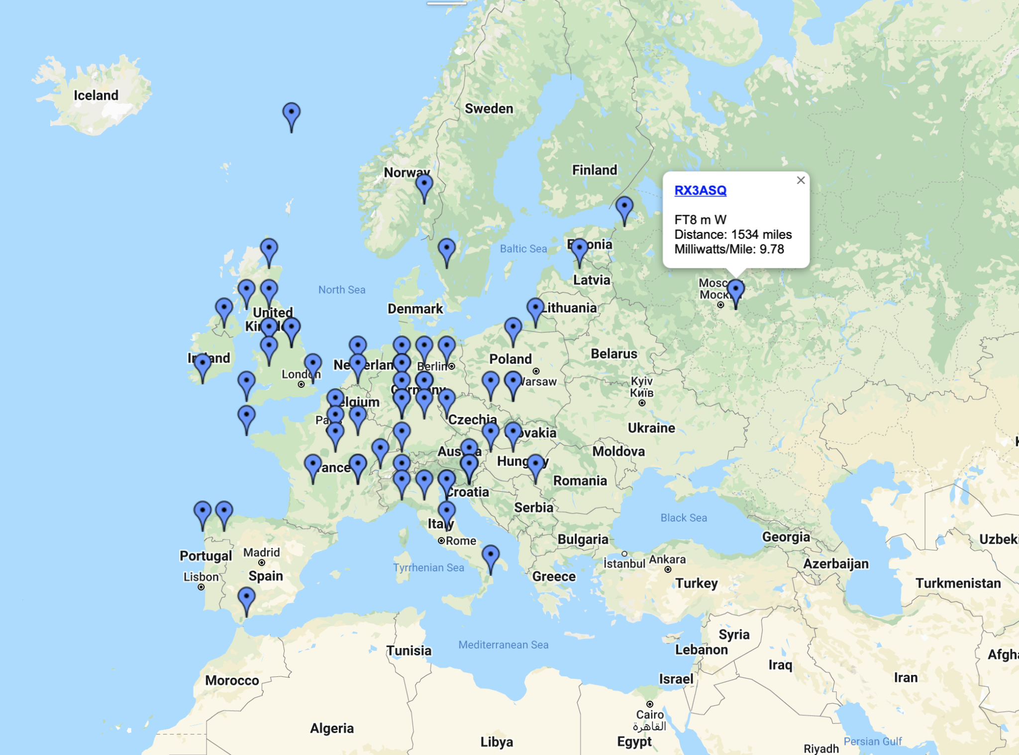
Map showing NVIS FT8 contacts on the 40m band

As you can see on the map above, 1534 miles was the best achieved, RX3ASQ just east of Moscow. The thing that pleased me most was the number of U.K. stations I could hear with the closest being just 43 miles away. Most European stations were easily worked even with reduced levels of power (10w) and so I’m hoping that this simple end fed NVIS antenna will become my goto antenna for local chatter on the 40m band.

What was very interesting was what I could hear on the antenna, I didn’t expect to hear any DX stations at all however, I was surprised to see stations from Mongolia, Japan and the USA popping up in the WSJT-X window.

Obviously I couldn’t get back to them as my angle of radiation was far too high to get a signal out over those distances but, it just goes to show what can be a heard on a very low long wire.

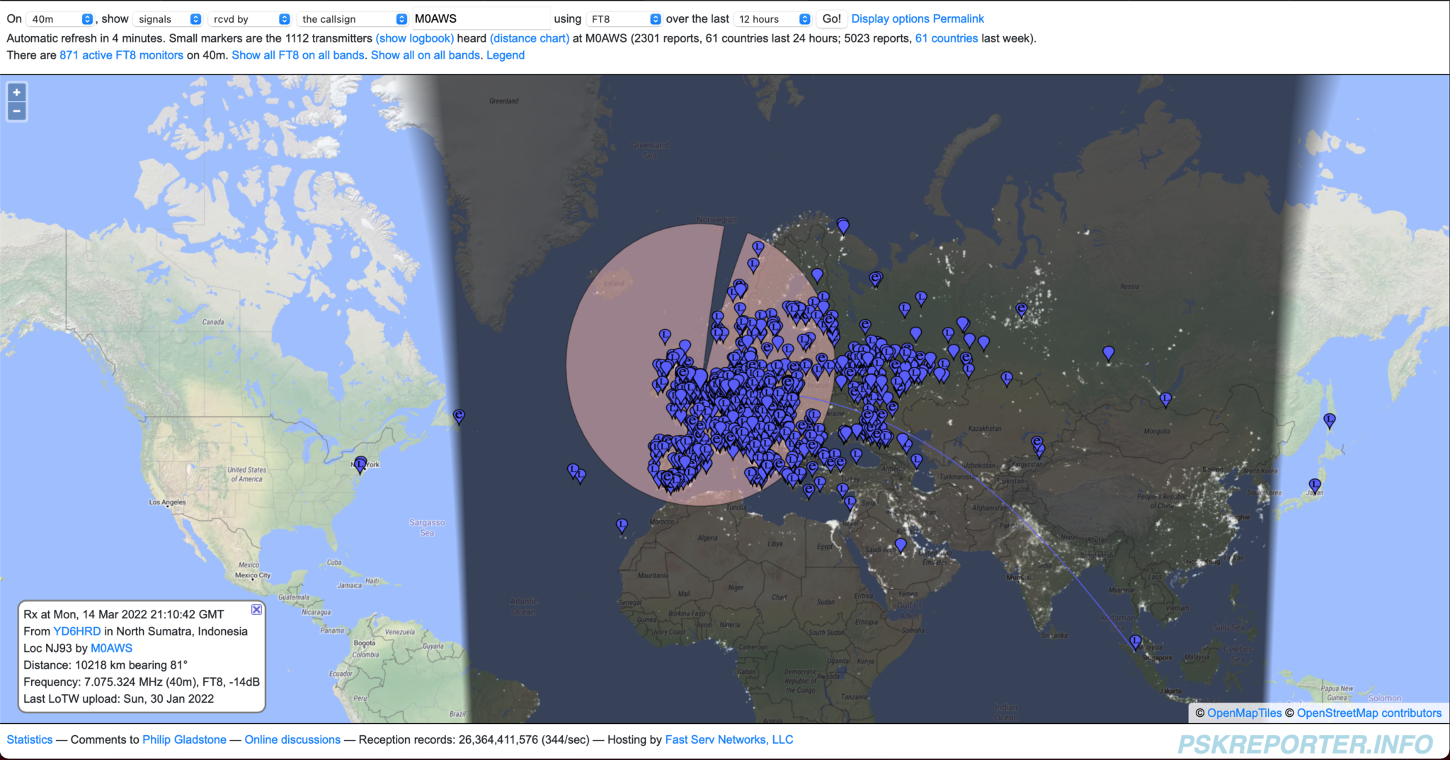
Map showing stations heard on 40m using NVIS antenna

By the end of the evening to my surprise I had been heard in the USA, I was amazed to see where I’d managed to get into with such a low antenna. The main cluster of stations were in the U.K. and Europe of course which is exactly what I wanted from this antenna.

Stations that heard M0AWS on 40m FT8 using NVIS antenna

So the next test will be on the 80m band, I’m hoping to get similar results on SSB with inter-G stations being easy to work. I doubt I will be able to get anywhere near the 1500 miles I achieved on the 40m band but, I’ll be more than happy with U.K. and EU stations.

More soon …
adi2html v0.6 release

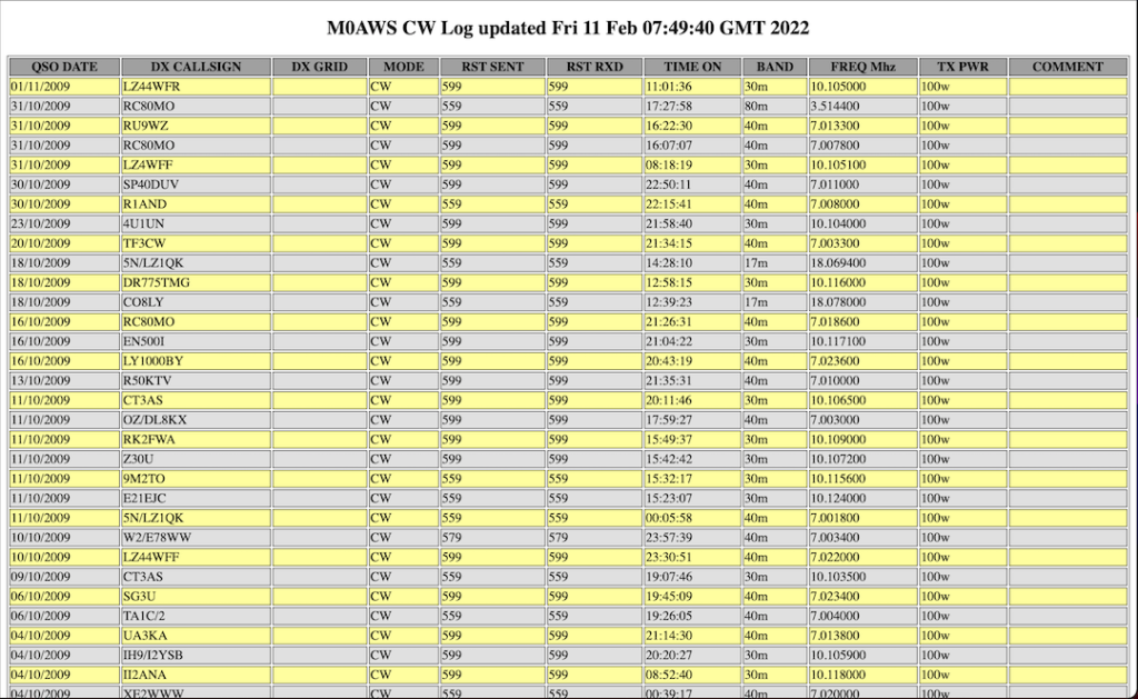
Following on from the adi2html v0.5 release I’ve now added a little more code to include a map of the contacts detailed in the wsjtx_log.adi file so that there is a visual representation of the data included in the webpage. (Map must be generated externally and JPEG/GIF/PNG uploaded to website to be included in the webpage).

See my WSJT-X log here

Just to recap, adi2html generates a HTML webpage from the wsjtx_log.adi file so that the log can be presented in a palatable format on a website.

As before the code can be downloaded using the link below.

If you use my code please consider leaving the footer in place so I get some credit, thanks!

Will raising my vertical antenna make it work better?

A question I get asked regularly is:

“Why don’t you mount your 20m EFHW Vertical antenna higher up in the air?
It’ll work much better the higher you get it”.

I have over the years tried raising and lowering my vertical antennas for DXing and found that keeping the base of the antenna and feed point low has advantages over a raised installation. I’ll try and explain this using some 3D and 2D far field plots from the EzNEC antenna modelling software that I use.

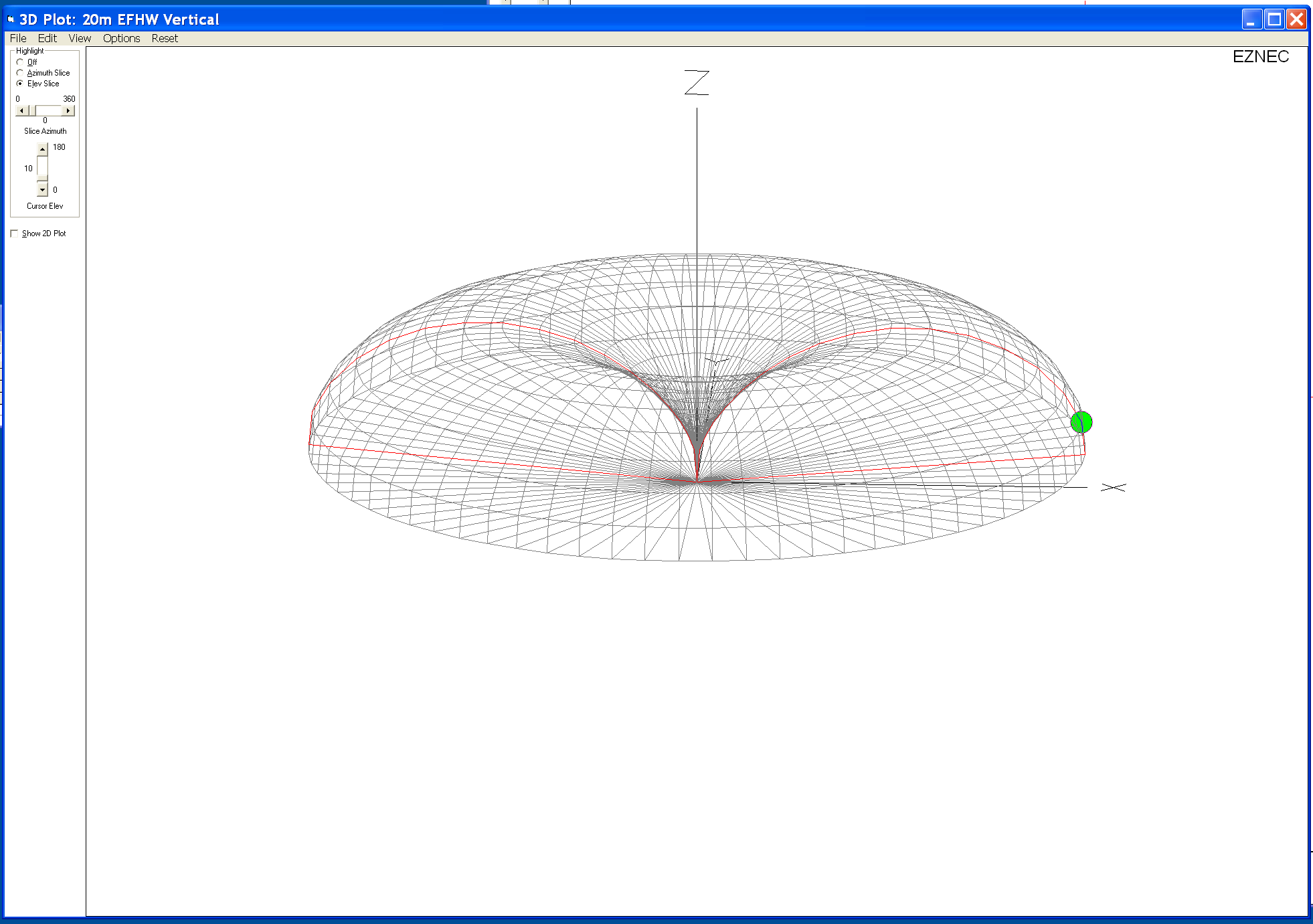
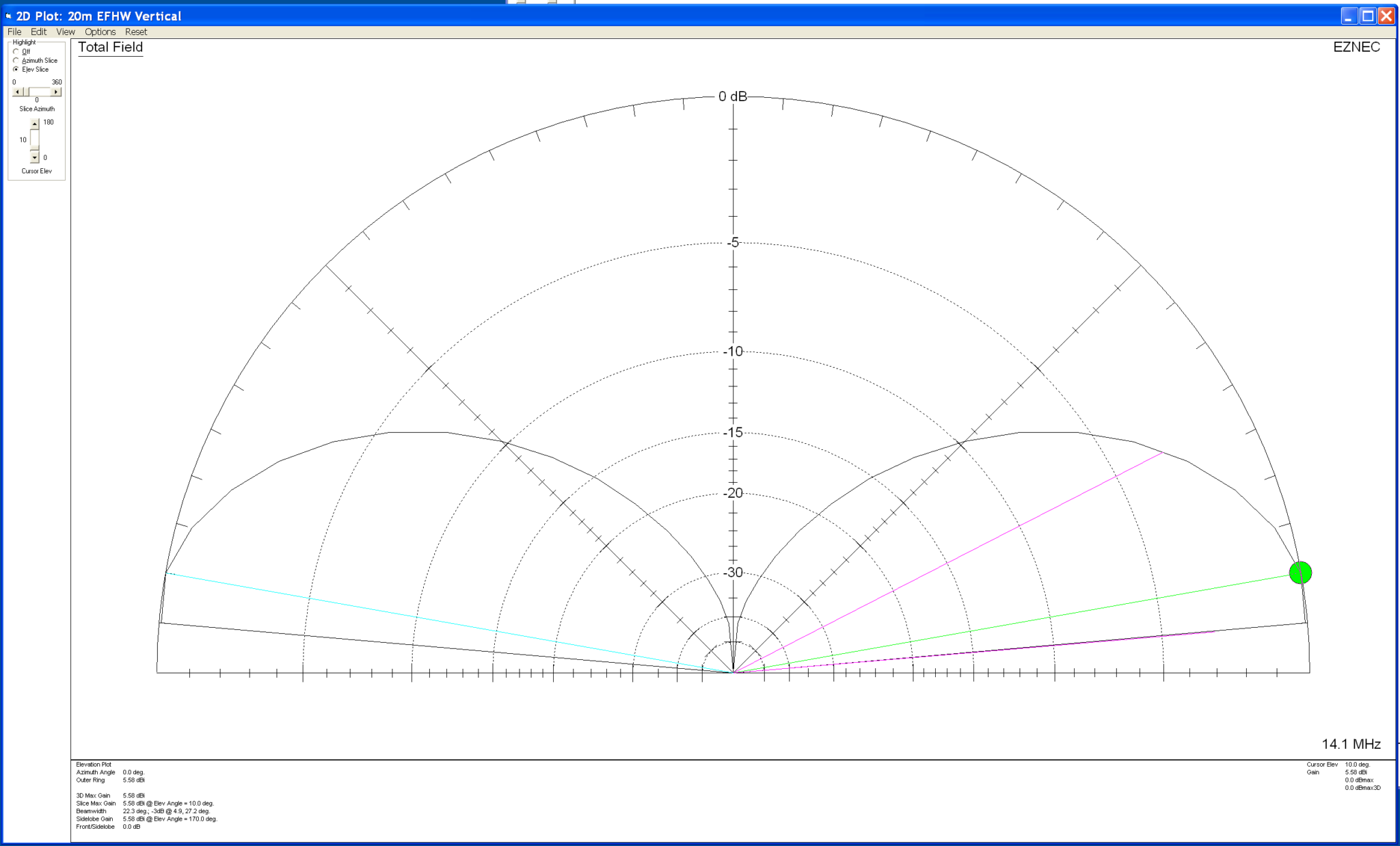
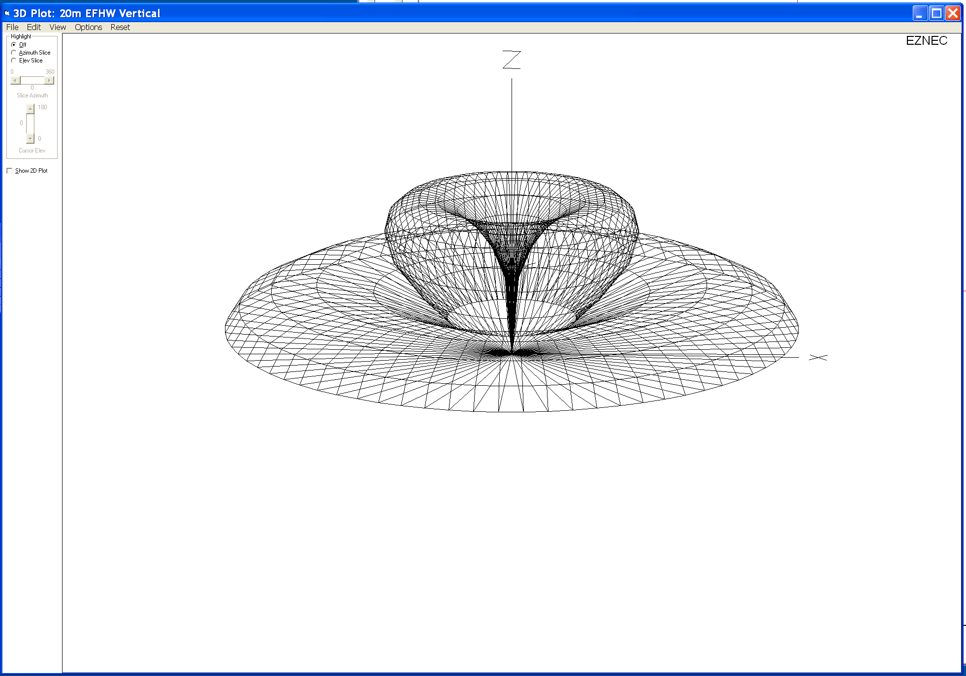
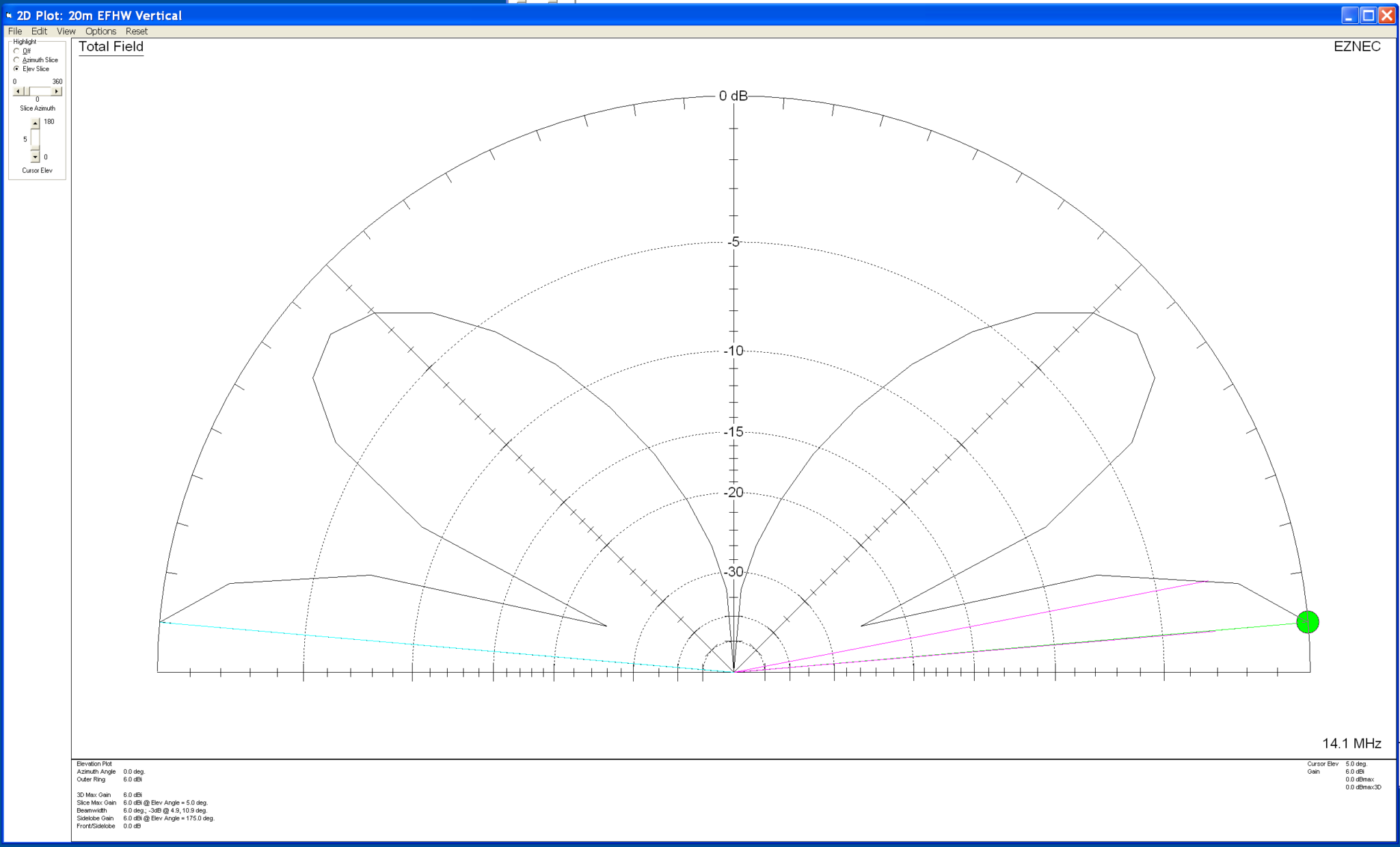
Below are the 3D and 2D far field plots as I have it setup at the moment. The 49:1 Unun is at ground level with the base of the antenna also at ground level.

20m EFHW vertical fed at ground level 3D Plot
20m EFHW vertical fed at ground level 2D Plot

Forgetting about the dBi gain figures for the time being and just concentrating on the overall radiation pattern you can see that with the antenna fed at ground level it has a typical circular radiation pattern with a deep null in the centre and a very low angle of maximum radiation. This makes the antenna perfect for DXing and is backed up by the success I’ve had on the 20m band working Australia, Thailand, Indonesia, South America, West Coast USA and Canada. This is exactly what I wanted and I’m extremely happy with it’s performance. I must add that I’m not looking to work European stations with this antenna, I’m only looking for DX stations especially those with very weak signals.

So now let’s take a look at what happens to the radiation pattern when we raise the antenna and the feed point above ground level.

First let’s raise the antenna so that the base and feed point are 3m above ground level.

20m EFHW Vertical with base and feed point 3m above ground 3D Far Field Plot
20m EFHW Vertical with base and feed point 3m above ground 2D Far Field Plot

Looking at the two far field plots above you can see that with the antenna and feed point raised by 3m we start to get some high angle lobes appearing in the centre of the radiation pattern. The overall maximum radiation is still at a low angle and so this would still be good for DXing but, does have an element of high angle radiation to it now. This will of course mean we’ll start to be able to work stations much closer to us and also be able to hear them better.

Raising the base of the antenna and feed point to 5m above the ground we see that the high angle lobes get even bigger and start to distort the overall radiation pattern of the antenna.

20m EFHW Vertical with base and feed point 5m above ground 3D Far Field Plot
20m EFHW Vertical with base and feed point 5m above ground 2D Far Field Plot

At 5m above ground the two high angle lobes have increased considerably which will result in more high angle radiation from the antenna. Maximum radiation is still at a low level though and so DXing will still be good with this setup but, from experimentation and experience I know that there are times when closer stations start to affect the ability to pick out the weaker DX stations. This is exactly what I don’t want.

Raising the antenna up even further to 10m above ground we get the following result.

20m EFHW Vertical with base and feed point 10m above ground 3D Far Field Plot
20m EFHW Vertical with base and feed point 10m above ground 2D Far Field Plot

At 10m above the ground the two high angle lobes shown on the 2D elevation far field plot are now almost as big as the main lobe below it. This means there will be considerable high angle radiation from the antenna which will result in the ability to communicate with stations much closer to your QTH rather than focusing just on the DX stations.

If you’re looking for the best of both worlds then getting your antenna up higher is the way to go, you’ll be able to work stations in the 300-1500 miles range with ease and the DX stations thousands of miles away.

From my experience there is one disadvantage with this in that the closer stations tend to drown out the weaker DX stations reducing the overall DX capability of the antenna and this is why I keep the antenna feed point at ground level. From experimentation and experience gained over the years I’ve found that keeping the antenna base and feed point at ground level gives me a better chance at working the DX than I have if I raise the antenna up higher.

As with everything in life there’s always a compromise!

So it really does depend what you want to use your antenna for. If like me you only want to chase those rare DX stations that are always difficult to get then keep the base of the antenna and feed point low. This will maximise the null in the centre of the radiation pattern and keep interference from “local” stations to a minimum. The draw back to this of course is that you won’t be able to work the closer stations when there is no DX around.

However, if you want the ability to work more “local” stations and the stronger DX stations raise your antenna and feed point up to a more suitable level above ground so that you obtain more high angle radiation from your vertical antenna. Then when there’s no DX around you’ll still be able to chat with the more local stations.

I hope this helps all the people that read my blog understand the choice I have made and why I keep the base of the antenna and feed point at ground level.

More soon …
Venturing onto the 4m Band

The 4m band isn’t a band that I’ve ever used before. The main reason for this is that I’ve never had a radio that had 4m capability built in. Most HF rigs today come with the 6m band but, very few have the 4m band, that is until now.

Having recently purchased a Yaesu FTDX10 I now have access to the 4m band with a max power of 50w. (You do need to reset the radio into UK mode to get the 4m band)

From reading online I understand that the 4m band is very much like the 6m band propagation wise but, with fewer users. Since the 2m and 70cm bands are completely dead in the Woodbridge area I thought that perhaps there might be a few local HAMs on the 4m band.

Now having a transceiver for the band I needed to think about an antenna too.

Searching online I came across an article by G4AQB referencing a 4m band antenna built by Tim, G6TM. Both of these articles incorrectly refer to the antenna design as an EFHW for 4m, it is in fact a Sleeved Dipole or sometimes referred to as an End Fed Vertical Dipole for the 4m band. If it was an EFHW it would have a very high impedance and would need a 49:1 Unun to match it to 50 ohm coax.

Since this antenna is just a dipole it presents an almost perfect impedance match to 50 Ohm coax without the need for any matching circuit.

Working from G4AQB’s build notes as detailed on his blog it’s very quick and easy to cut the coax to the right length, strip part of the outer shield and create the choke using 8 turns of the same coax cable.

Since I wanted to make this a permanent fixture in the garden I decided to make an enclosure for the antenna so that it is weather proof and easy to mount.

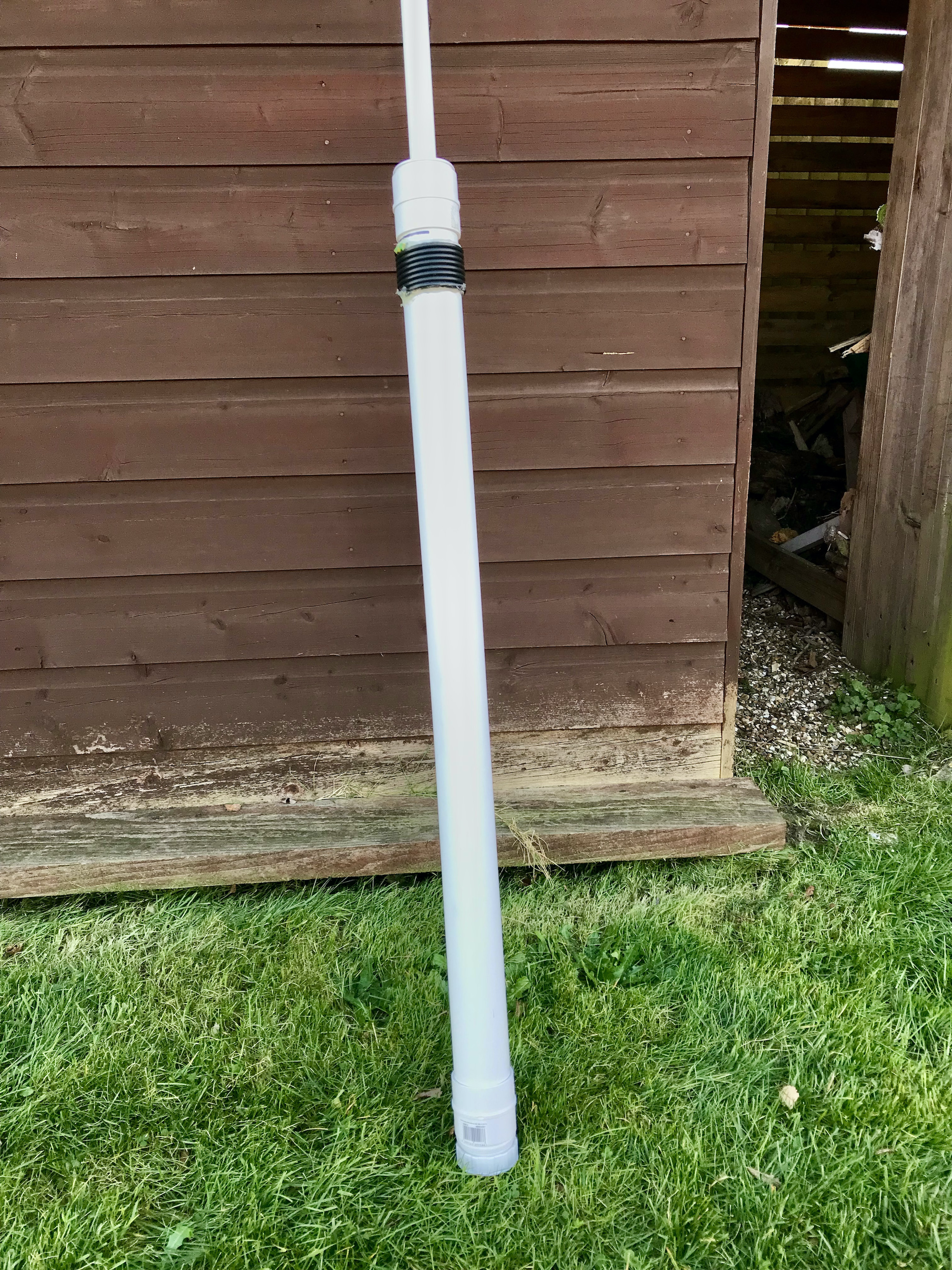
Using a mix of 25mm conduit, 50mm plastic tubing, a screw cap and a reducer I put together a very tidy 4m band sleeved dipole vertical antenna.

Home brew 4m sleeved dipole in plastic enclosure

Looking at the photo above you can see I used the 25mm conduit to house the sleeved dipole, I then used a reducer to join the 50mm tube to the 25mm conduit. Drilling two holes in the 50mm tube I brought the coax out and wound it 8 times around the tube to form the choke coil and then passed the coax back into the 50mm tubing so that it continued down to the SO239 socket on the bottom cap. I used some hot glue to hold the choke coil in place.

SO239 mounted in the bottom of the 50m tubing

I strapped the antenna to the top of the washing line post to check the SWR and found it’s a perfect match. With an SWR of 1:1 at the bottom of the band and 1.1:1 at the top of the band.

Overall I’m really pleased with the simple design and build.

I listened to the 4m band for a few hours whilst doing other things and didn’t hear a single soul, I do hope it’s not dead like the 2m band!

More soon …
Falklands Calling …

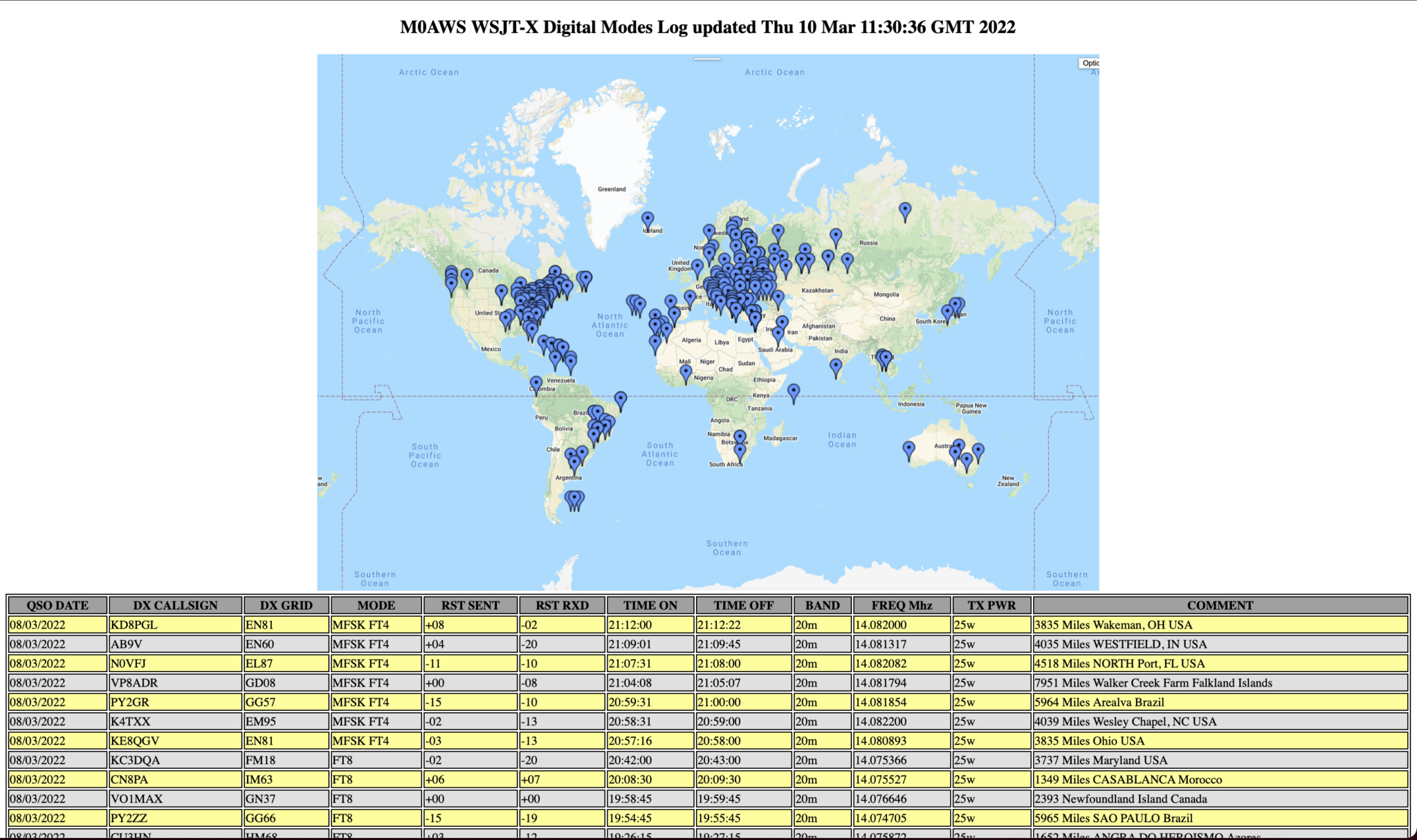
When I lived in France (F5VKM) I was totally focused on the low bands. I spent years trying to get the Falkland Islands on 160m. Now living in the UK with a typical small garden I no longer have the luxury of big antennas. Currently I’ve just got my EFHW Vertical for 20m at the end of the garden.

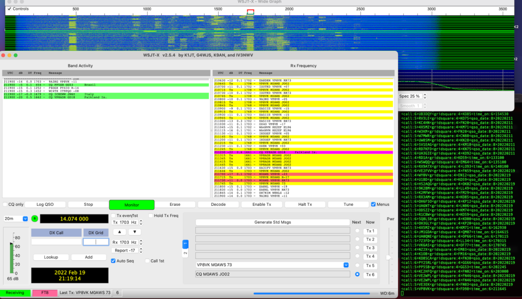
Today I heard the Falkland Islands on 20m for the first time since setting up the new station, I was amazed to say the least.

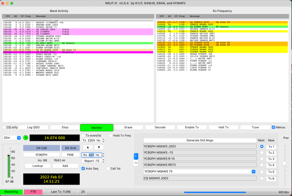
WSJT-X FT8 working VP8VK with just 25w

I decided to give the two stations a call, didn’t get an answer from VP8ADR but, VP8VK then popped up and I snuck in and got a quick QSO with just 25w.

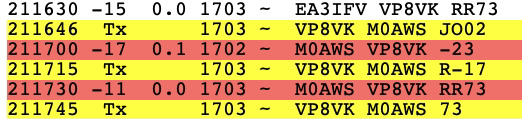
FT8 QSO with VP8VK

Working DX is so much easier on 20m than it is on 160m, I’m amazed!

-23dB is very close to the limit for FT8 but, it was enough to get a complete QSO and the Falklands in the log.

I also got VK6AS on 20m FT8 today, again with just 25w. This EFHW Vertical for 20m really is an excellent DX antenna, it’s perfect for the small garden too!

All stations heard FT8 20m

More soon …
Convert your RUMLogng radio logs to HTML

I’ve started using RUMLogng for logging on my MacBook Pro as it seems to be the most common logbook to use on the Apple Mac platform. I must admit that I’m not sure if I’ll carry on using it going forward as I’m not overly enamoured by it but, for the time being it’s all I have.

To get my logs on the blog I’ve written a small BASH shell script that reads the exported ADIF file from RUMLogng and creates a log in HTML format for each different mode.

You can see the output of the BASH script by selecting a log from the Logs menu at the top of this page.

If you want to be able to add your log to your own website then I’ve made the script available for download below.

Currently I’ve only tested the script with the few different modes that I have log entries for but, it should work for all modes. If you find any issues please contact me with all the details and I’ll look into resolving any problems.

As always, if you use my code to generate webpages on your website please consider leaving the footer in place so I get some credit, thanks!

FTDX10, Apple Computers and the USB Audio Chain

One of the things I’ve had issues with ever since purchasing the Yaesu FTDX10 transceiver is control of the audio chain via the USB connection on the rear of the radio.

The output from the radio into my Macbook Pro is just too high, WSJT-X is constantly pushed beyond the green zone and often into the red zone when monitoring FT8 signals with the AGC off. The only way to cure this is to keep the AGC on Auto which sometimes results in not hearing the very weak DX stations due to the AGC not reacting fast enough. Putting the AGC on fast causes the red line to be hit far too often once more.

Sadly, the USB Audio Codec doesn’t provide any volume adjustment on audio coming from the radio into the MacBook Pro thus, it’s just full volume all the way. This is a flaw in the codec design and really does need to be resolved long term.

Looking at the audio going the other way, that is from the MacBook Pro into the radio via the USB port fortunately there are gain controls available both on the MacBook Pro and on the radio itself.

Ever since venturing into the world of WSJT-X & FT8/4 I’ve had an issue with only being able to move the PWR slider in the WSJT-X up to the first marker at the bottom of the screen, anymore and the ALC on the radio goes off the scale instantly!

So yesterday I decided to investigate the audio chain into the radio more thoroughly and see what could be done about the levels.

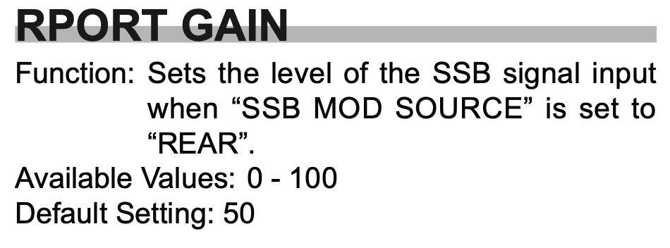
Looking at the radio manual I found that there is an RPORT GAIN setting in the menu system that can be used to alter the amount of gain applied to the incoming audio signal on the USB port in the radio.

FTDX10 Rport Gain entry in the manual

As detailed in the manual, the default setting for this is 50 in a range of 0 to 100. So that’s a 50% increase in gain applied to the incoming audio at the radio end, that’s quite a boost! (The gain is applied both in SSB and Data Modes)

I decided to experiment reducing this figure to see if it gave me greater control over the audio output from WSJT-X via the PWR control. This did indeed help however, there was still too much audio coming into the radio from the MacBook Pro and so I needed to look further along the audio chain.

Moving back onto the MacBook I opened the Midi App and took at look at the Output controls for the USB Audio Codec, sure enough this was set to max for both channels, not good.

Reducing the levels in the midi app started to make much more of a difference, I could now raise the audio level using the PWR control in WSJT-X without things immediately going wild and could now control the levels with a far greater level of granularity than ever before.

After much tinkering I eventually found the levels whereby I could drive the rig to the selected output power (20w) without the ALC going off the scale and the signal becoming horribly distorted, there was calm in my audio chain once more.

So what settings did I settle on?

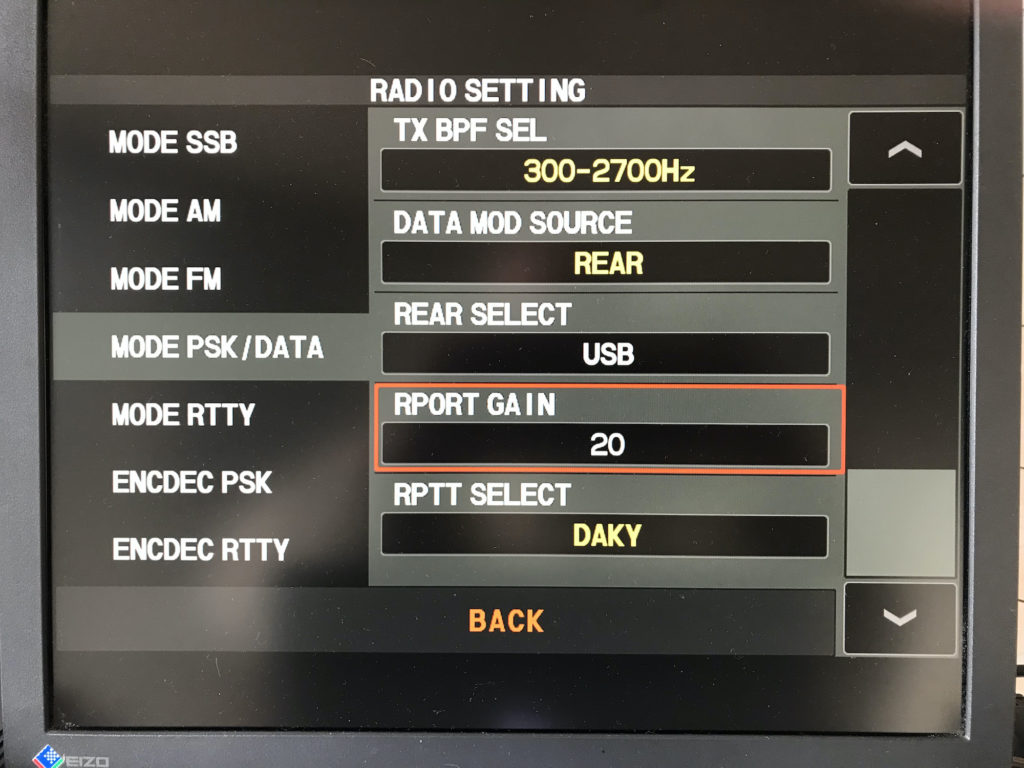
On the radio itself I wound down the RPORT GAIN setting from 50 to 20, this reduced the amount of gain applied to the audio coming in on the USB port considerably and helped to tidy up the FT8 signal.

FTDX10 RPORT GAIN Setting reduced from 50 to 20

It’s great that there is the facility on the radio to reduce the gain on the inbound audio signal, if only Yaesu would do the same for the outbound audio level.

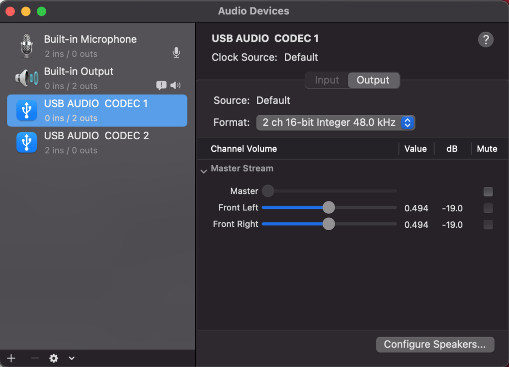
Next, on my MacBook Pro via the Midi app I reduced the output level on the USB Audio Codec from the default maximum down to 0.494 (-19). This stops the audio level from being too high going into the radio and removes all distortion from the resulting signal.

Midi App on Macbook Pro showing reduced audio output

Once these small changes have been made it becomes necessary to raise the PWR level in the WSJT-X app to roughly the centre position. At this point the radio gets a clean, distortion free audio input whilst driving the radio to the full 20w output with no movement on the ALC whatsoever.

I found I could move anywhere on the frequency spectrum on FT8 without any of the levels changing and with the ALC not moving whilst the radio delivered the full 20w output.

I also checked FT4 mode as it is an MFSK mode to see if these settings worked for it too and I’m glad to say it worked perfectly! (I also found I really liked FT4!)

WSJT-X with the PWR setting at roughly 50%

Altering the PWR level in WSJT-X doesn’t have the huge effect it had before and now it’s very easy to adjust the level without the ALC going off the scale in an instant.

It took me about an hour or so to get this just right but, it was well worth the time invested.

I hope this is of use to other Apple Mac computer users in the HAM community.

More soon …