Since setting up the new HAM station here in the UK the one band I’ve not yet got back onto is 160m, one of my most favourite bands in the HF spectrum and one that I was addicted to when I live in France (F5VKM).
Having such a small garden here in the UK there is no way I can get any type of guyed vertical for 160m erected and so I needed to come up with some sort of compromise antenna for the band.
Only being interested in the FT4/8 and CW sections of the 160m band I calculated that I could get an inverted-L antenna up that would be reasonably close to resonant. It would require some additional inductance to get the electrical length required and some impedance matching to provide a 50 Ohm impedance to the transceiver.
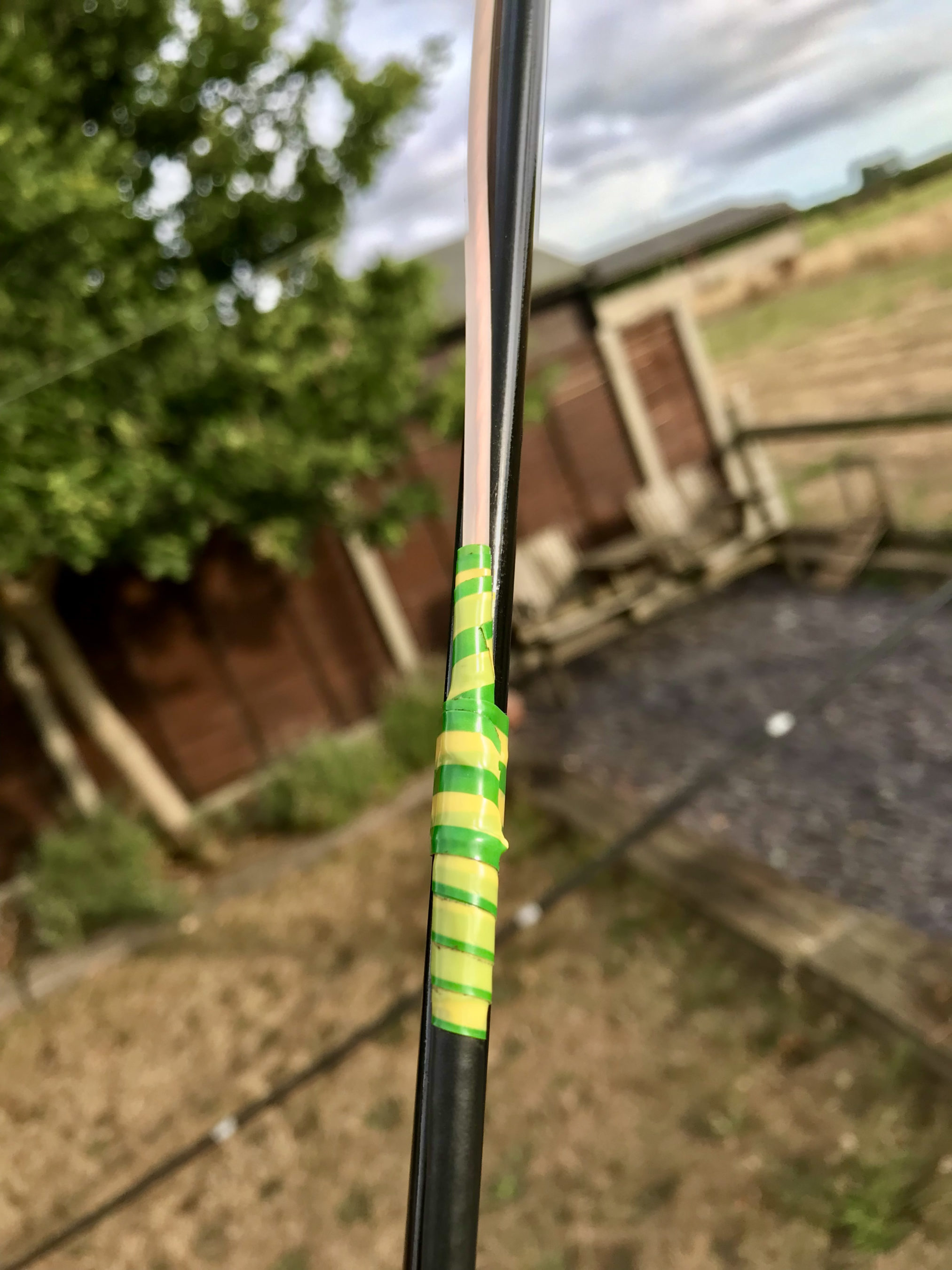
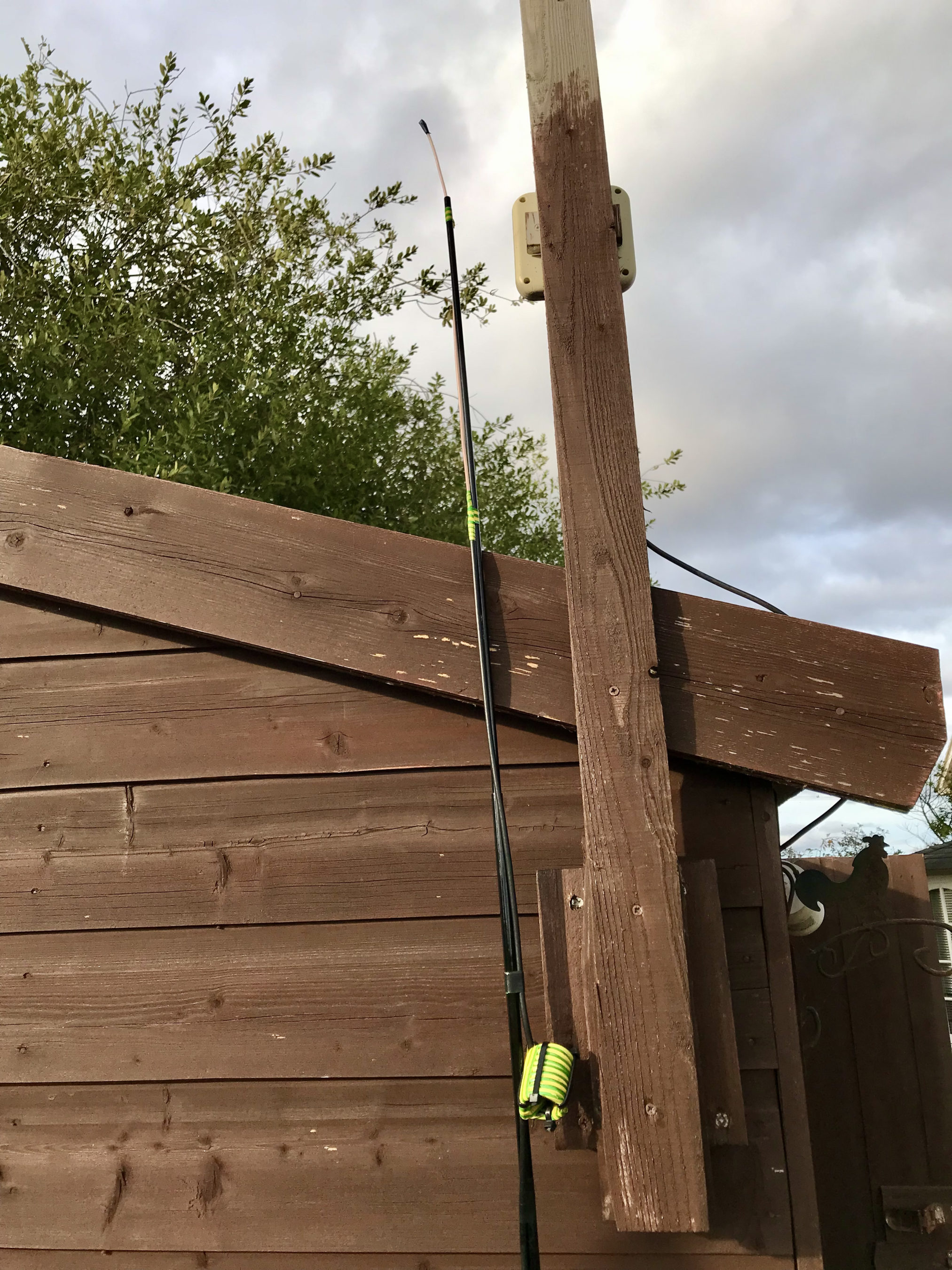
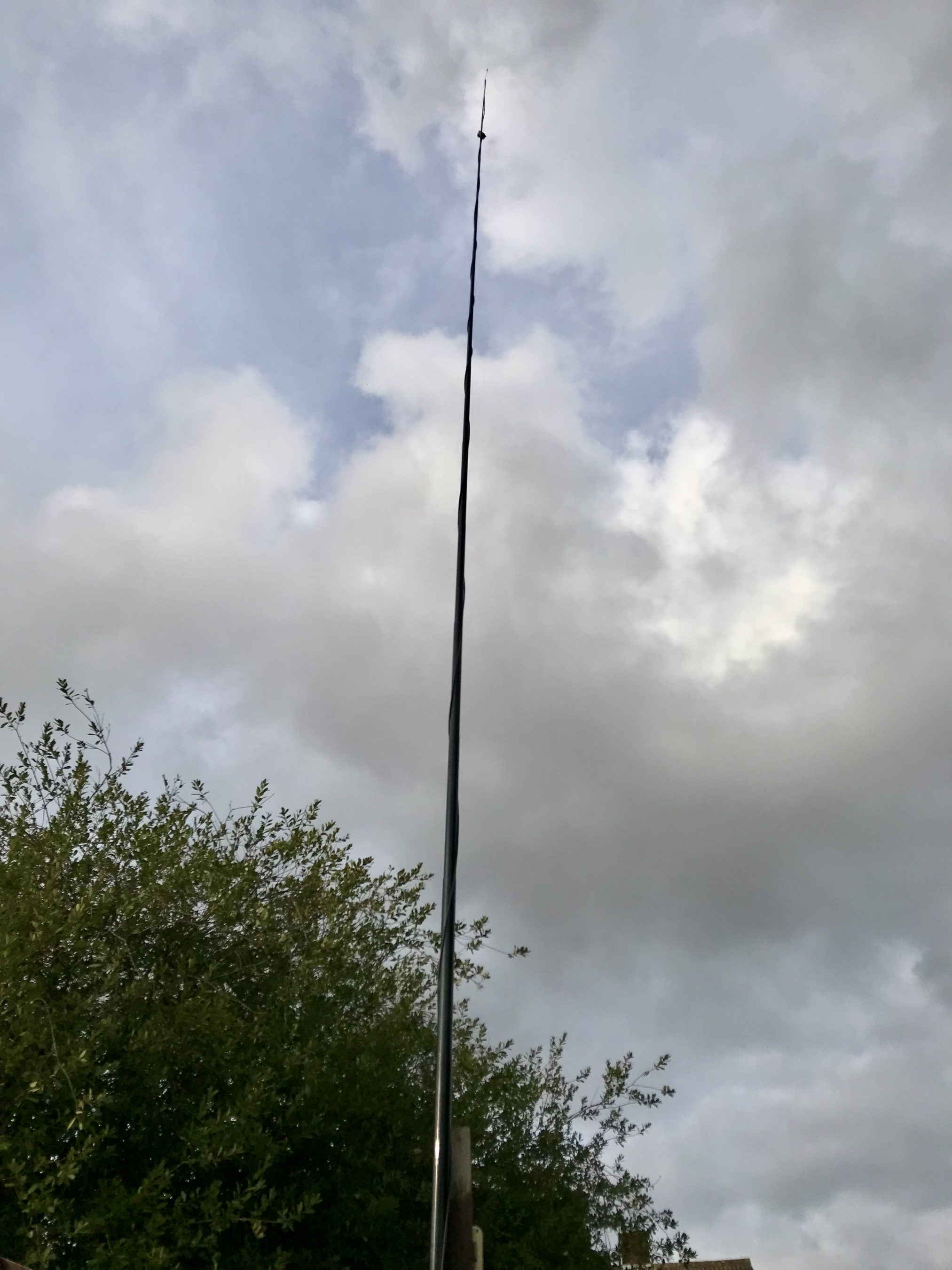
Measuring the garden I found I could get a 28m horizontal section in place and a 10m vertical section using one of my 10m spiderpoles. This would give me a total of 38m of wire that would get me fairly close to the quarter wave length.
For impedance matching I decided to make a Pi-Network ATU. I’ve made these in the past and found them to be excellent at matching a very wide range of impedances to 50 Ohm.
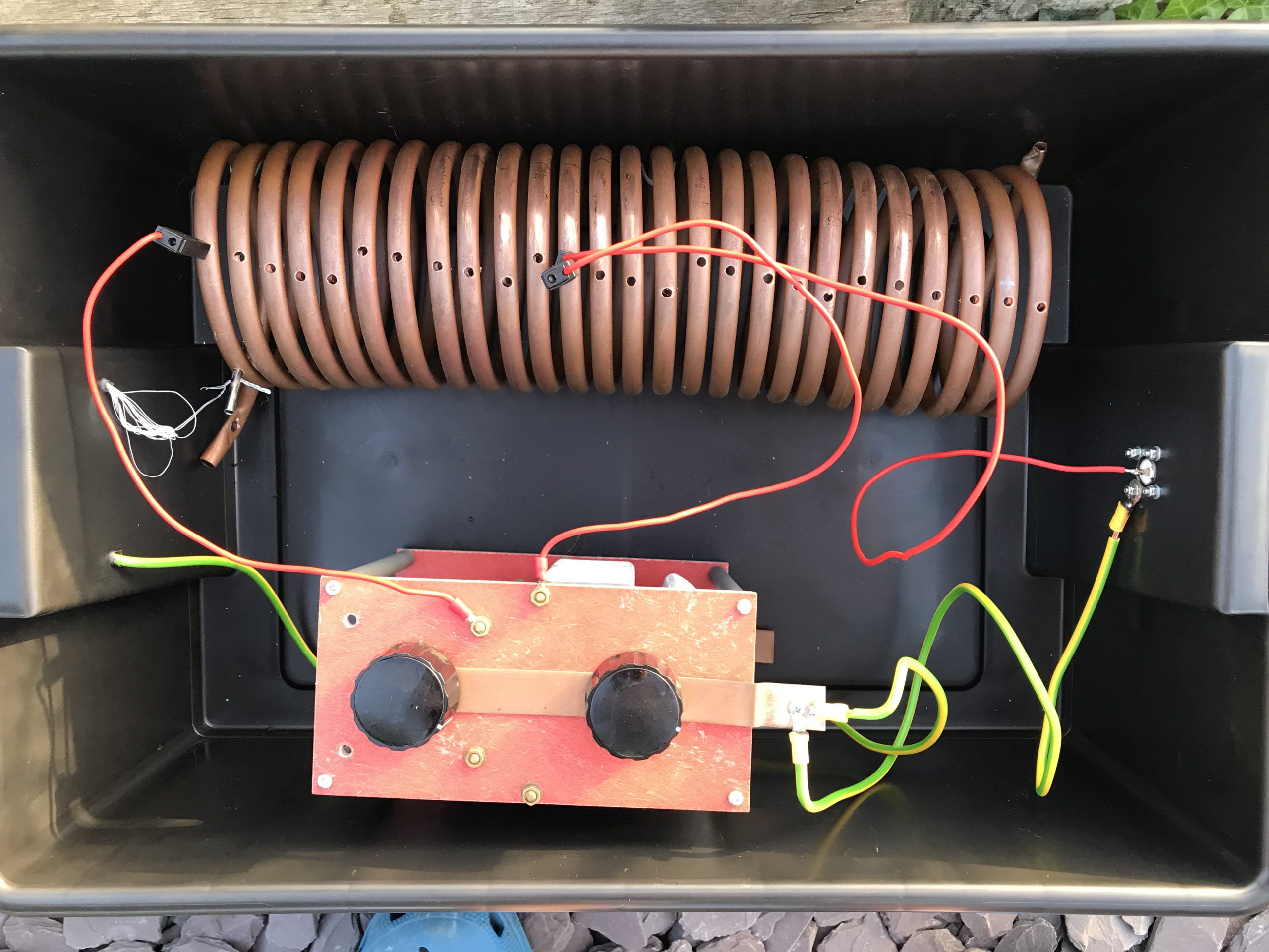
M0AWS Homebrew Pi-Network ATU
Since I still had the components of the Pi-Network ATU that I built when I lived in France I decided to reuse them as it saved a lot of work. The inductor was made from some copper tubing I had left over after doing all the plumbing in the house in France and so it got repurposed and formed into a very large inductor. The 2 x capacitors I also built many years ago and fortunately I’d kept locked away as they are very expensive to purchase today and a lot of work to make.
Getting the Inverted-L antenna up was easy enough and I soon had it connected to the Pi-Network ATU. I ran a few radials out around the garden to give it something to tune against and wound a 1:1 choke balun at the end of the coax run to stop any common mode currents that may have appeared on the coax braid.
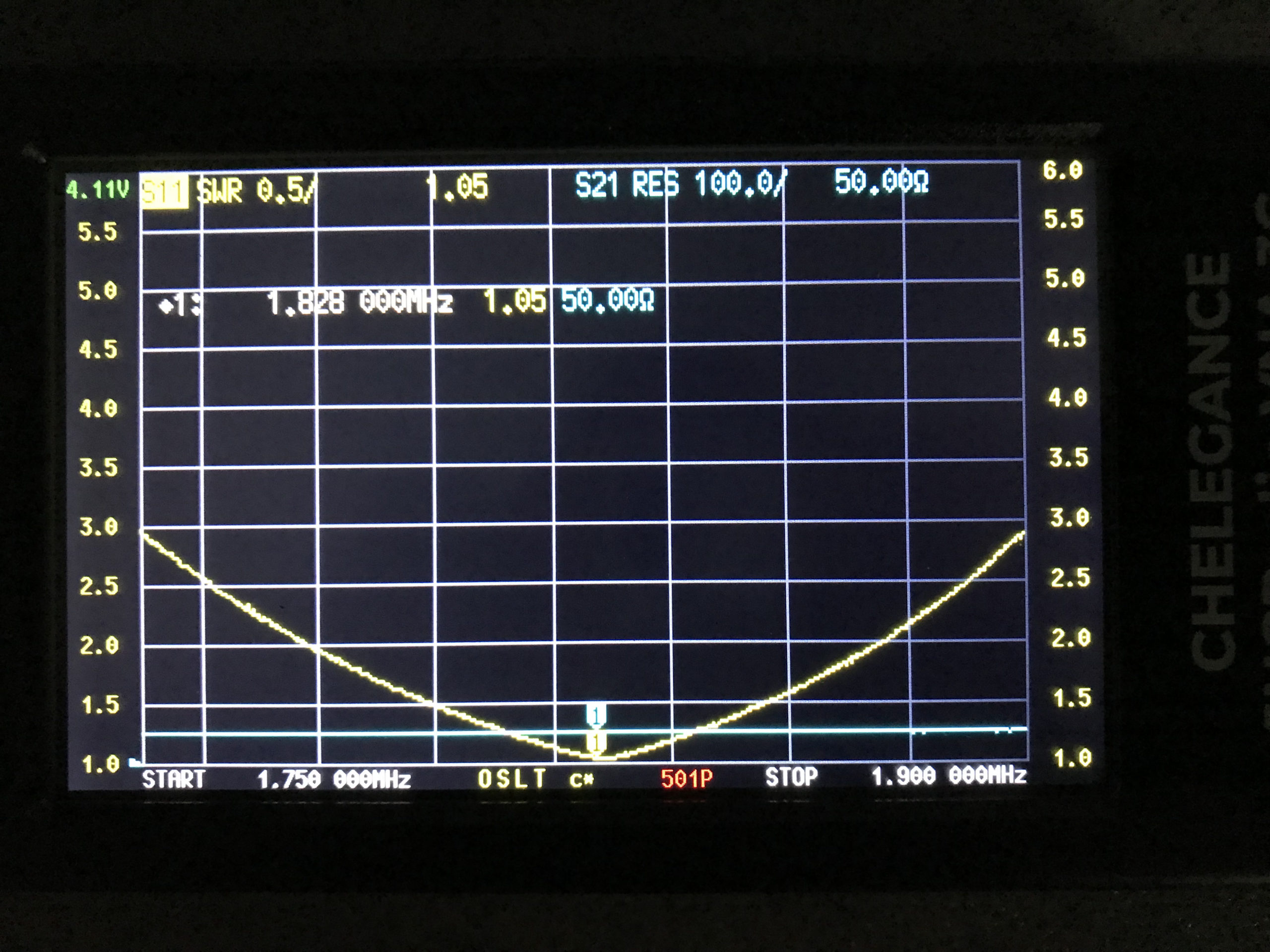
Connecting my JNCRadio VNA I found that the Inverted-L was naturally resonant at 2.53Mhz, not too far off the 1.84Mhz that I needed. Adding a little extra inductance and capacitance via the ATU I soon had the antenna resonant where I wanted it at the bottom of the 160m band.
M0AWS 160m Inverted L Antenna SWR Curve
With the SWR being <1.5:1 across the CW and FT8 section of the band I was ready to get on 160m for the first time in a long.
Since it’s still summer in the UK I wasn’t expecting to find the band in very good shape but, was pleasantly surprised. Switching the radio on before full sunset I was hearing stations all around Europe with ease. In no time at all I was working stations and getting good reports using just 22w of FT8. FT8 is such a good mode for testing new antennas.
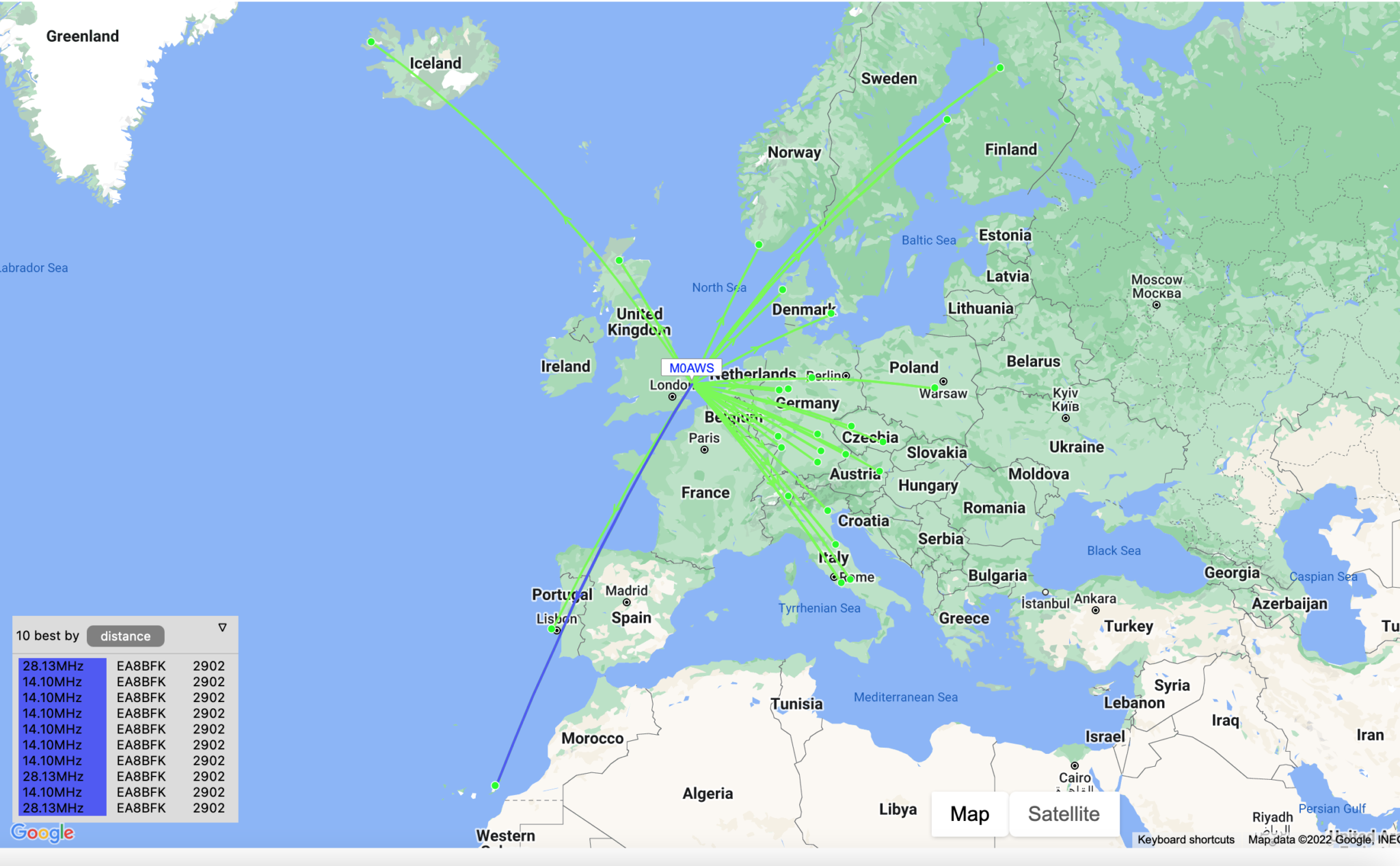
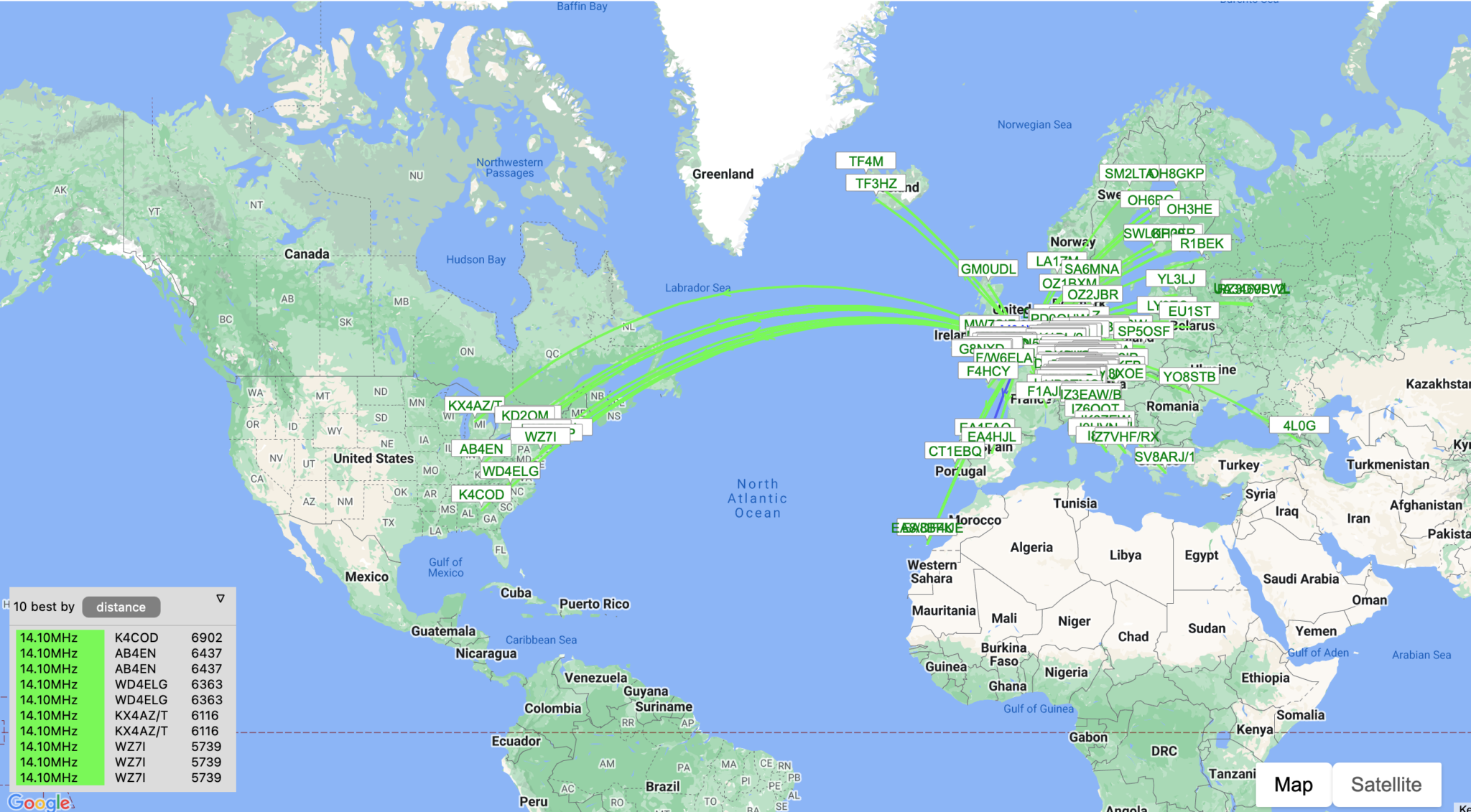
As the sky got darker the distance achieved got greater and over time I was able to work into Russia with the longest distance recorded being 2445 Miles, R9LE in Tyumen Asiatic Russia.
In no time at all I’d worked 32 stations taking my total 160m QSOs from 16 to 48. I can’t wait for the long, dark winter nights to see how well this antenna really performs.
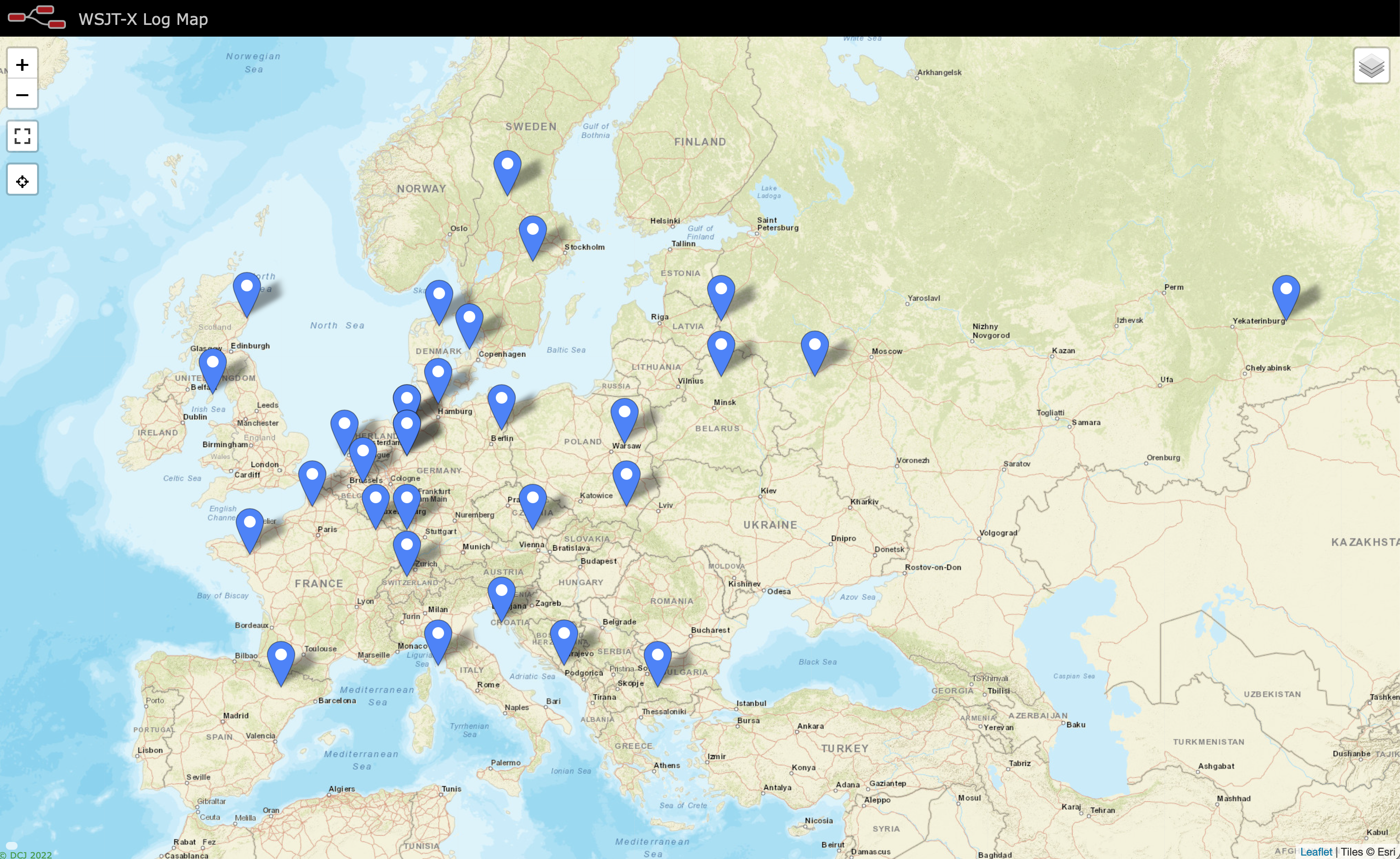
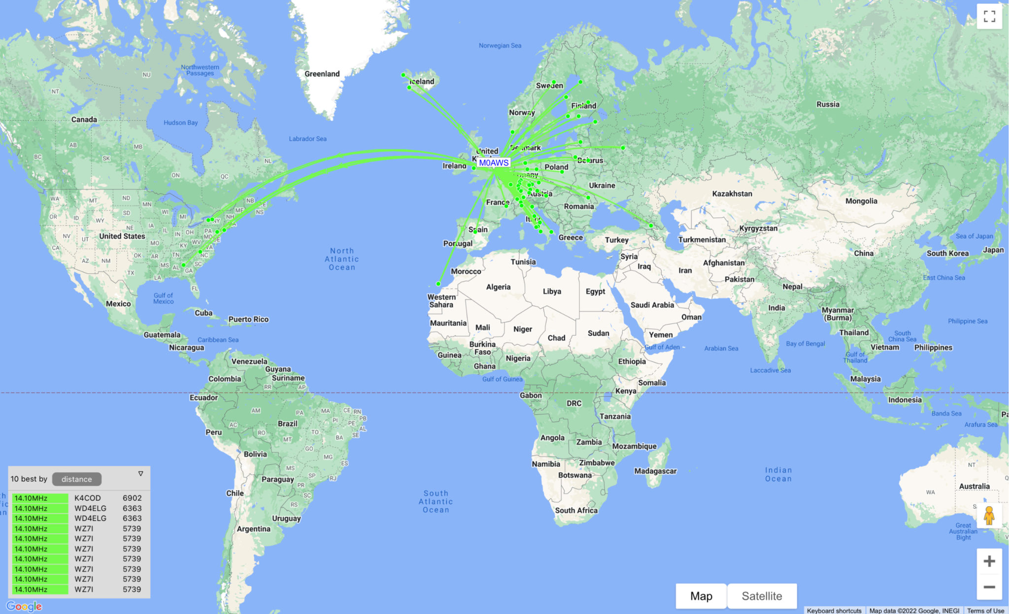
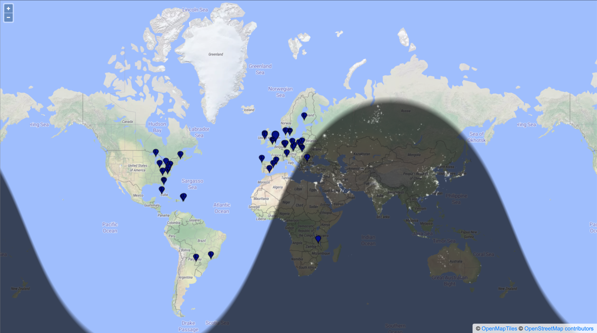
M0AWS Map showing stations worked on 160m using Inverted L Antenna
The map above shows the locations of the stations worked on the first evening using the 160m Inverted-L antenna. As the year moves on and we slowly progress into winter it will be fun to start chasing the DX again on the 160m band..
UPDATE 6th October 2023. Been using the antenna for some time now with over 100 contacts on 160m. Best 160m DX so far is RV0AR in Sosnovoborsk Asiatic Russia, 3453 Miles using just 22w. Pretty impressive for such a low antenna on Top Band.
This is a 15m band delta loop design that I’ve put together as requested by Wim, PE1PME.
The 15m band delta loop follows exactly the same design principles as all the other delta loop designs I’ve already put on the website. They are designed such that they present a 50 ohm impedance at the feed point and thus have no requirement for complex impedance matching circuits/transformers.
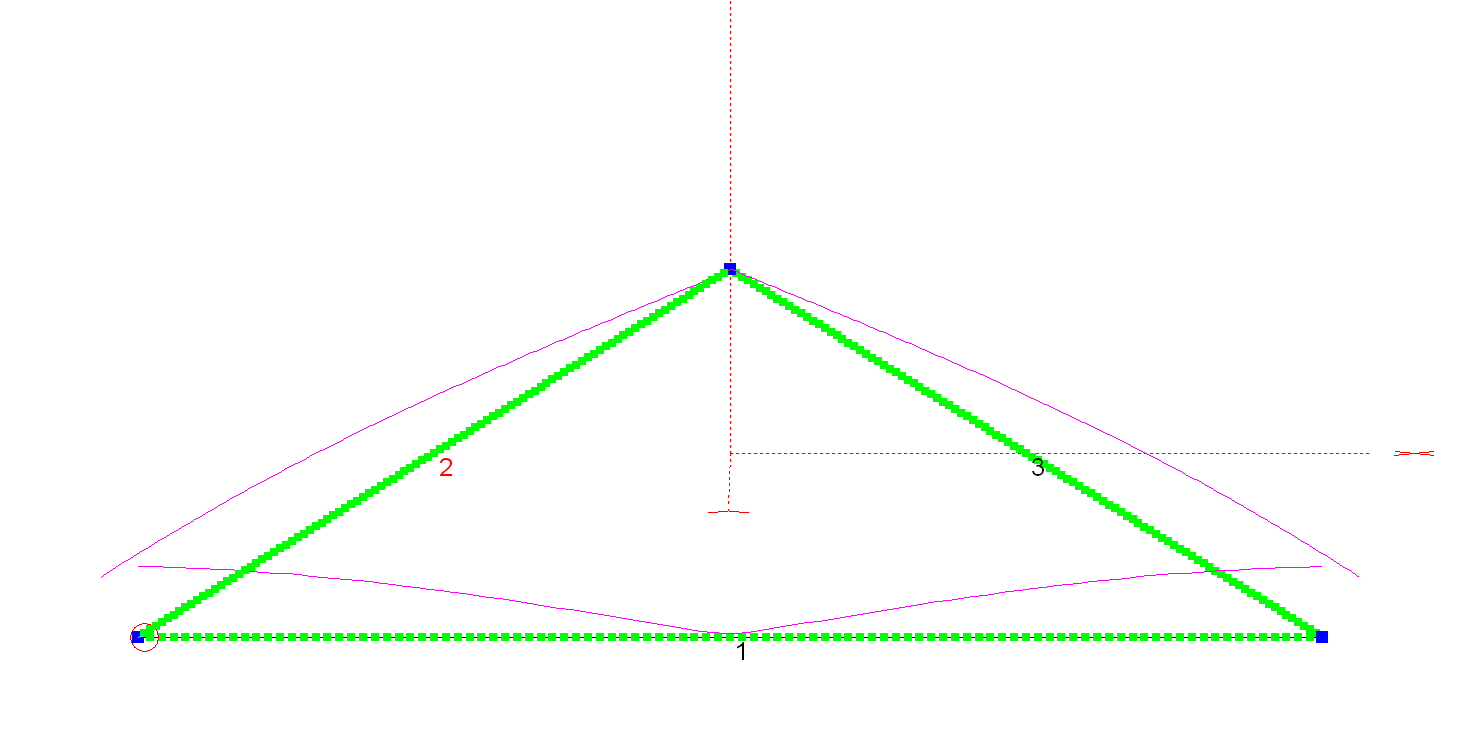
15m Band Delta Loop Antenna View
The dimensions for the antenna are as follows:
Wire 1 – Horizontal exactly 1m above the ground for its entire 7m length. Wires 2 & 3 are exactly 4.12m long each with the top being 3.18m above the ground.
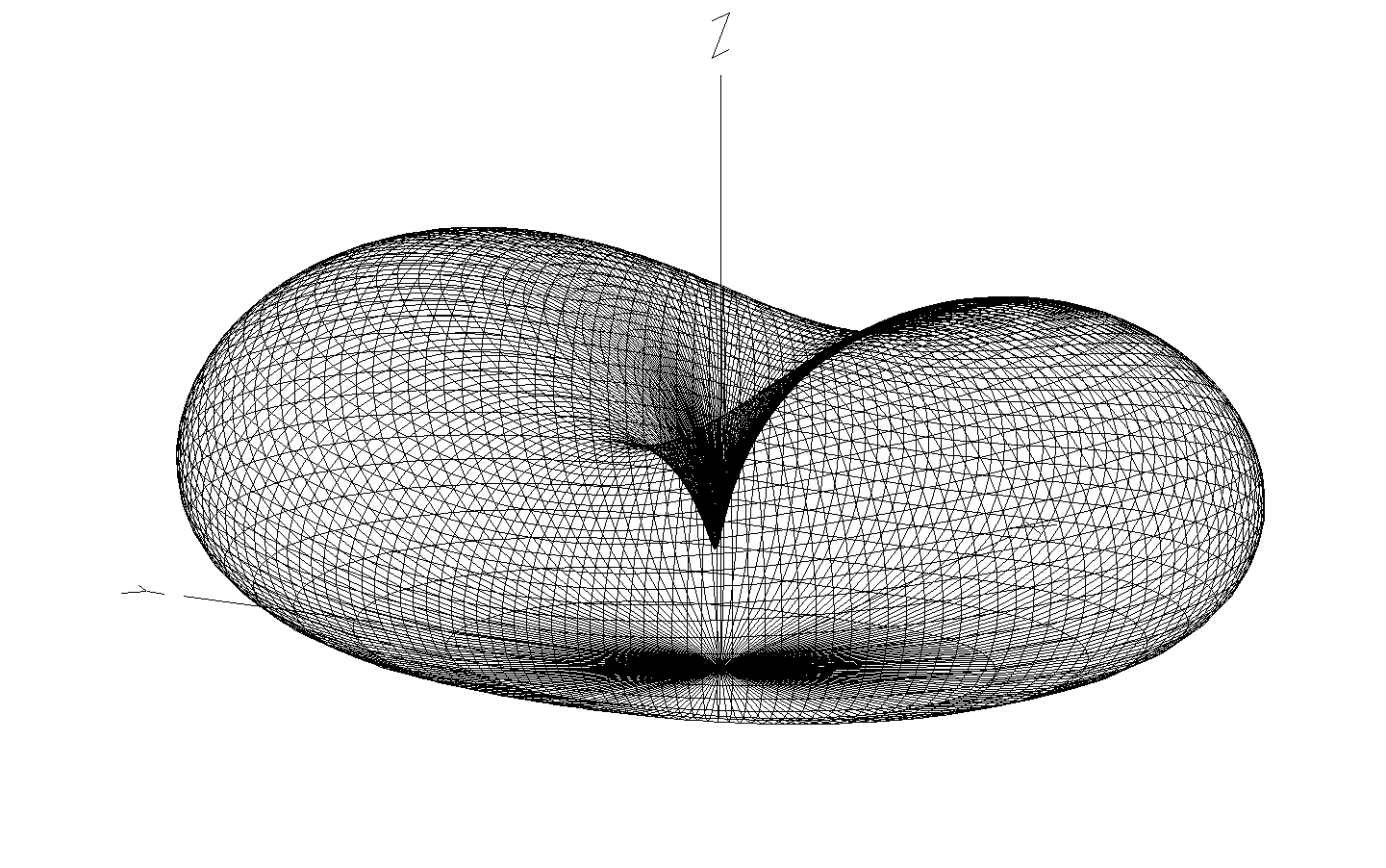
15m Band Delta Loop Antenna 3D Far Field Plot
The 3D far field plot shows a typical delta loop radiation pattern with the maximum radiation through the loop and a deep null in the centre.
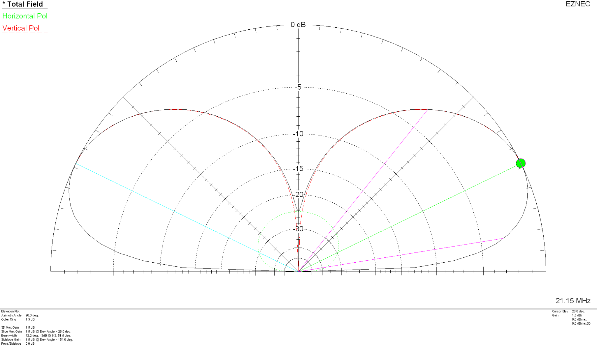
15m Band Delta Loop Antenna 2D Far Field Plot
The 2D elevation plot shows that the antenna will give a maximum gain of 1.5dBi at 26 degrees with useful gain at lower angles.
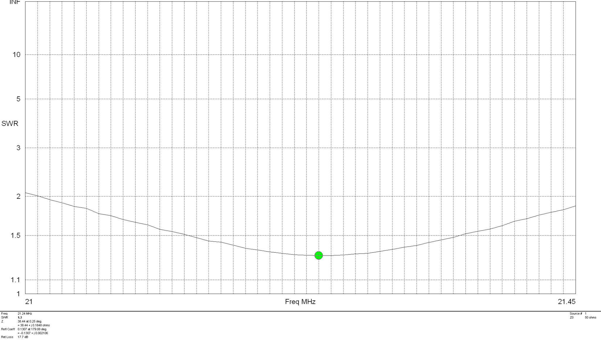
The SWR plot shows that the antenna will have a fairly wide bandwidth and match to 50 ohm coax extremely well. The antenna is designed to be fed in one of the lower corners via a 1:1 balun for best results.
15m Band Delta Loop Antenna SWR Curve
Summary:
Total Wire Length: 15.24m Horizontal Wire Length: 7m @ 1m above ground Diagonal Wire Lengths: 4.12m Wire Dia: 2.5mm Height at Centre: 3.18m Feed Type: 1:1 Balun in bottom corner (Can use coax if necessary) Impedance: 50 Ohm SWR: <1.5:1 at resonance
I’ve been gradually building my QO-100 ground station over the last few months and have had the receive path working for some time now. One of the things I really miss with the Funcube Dongle Pro+ (FCD) SDR is a real VFO knob for changing frequency.
My QO-100 Node Red dashboard is configured so that I can have the FCD track the uplink frequency from the IC-705 but, sometimes I use the FCD without the IC-705 in the shack and so a physical VFO would be handy.
Many years ago when I lived in France (F5VKM) I had a Flexradio Flex-3000 SDR, a great radio in it’s time and one that gave me many hours of enjoyment. One addition I bought for that station was a Griffin Technology Powermate VFO knob. It worked extremely well with the PowerSDR software for the Flex-3000 and I used it for many years.
Many years later I’m back in the UK and much of my equipment is packed away in the attic, including the Griffin Technology Powermate VFO.
I decided to dig it out and see if I could get it working with GQRX SDR software. Sadly I couldn’t get it working with GQRX however, I did find a way of getting it working with Node Red and thus could add it to my QO-100 Node Red Dashboard and then control GQRX with it via a simple Node Red flow.
Griffin Technology Powermate VFO
Plugging the Powermate VFO into my Kubuntu PC it wasn’t immediately recognised by the Linux O/S. After a little searching I found the driver on Github. I added the PPA to my aptitude sources and installed the driver using apt.
Once installed the default config for the Powermate device is to control the default audio device volume. To make the device available for use as a VFO knob you need to change the configuration so that the default setting is disabled. To do this is relatively easy, just edit the config file using your favourite command line editor (Vi/Vim in my case) and add the following entry.
vi /etc/powermate.toml

# Entry to control HDMI volume with Powermate
#sink_name = "alsa_output.pci-0000_01_00.1.hdmi-stereo"

# Set powermate not to work with volume control
sink_name = ""
As shown above, comment out the default “sink_name” entry (Yours may be different depending on audio device in your PC) and add in the Powermate “sink_name” entry that effectively assigns it to nothing.
Once this is done, save the file and exit your editor and then reboot the PC.
Next you’ll need to install a small program called evtest.
sudo apt install evtest
To check the evtest program has installed correctly, plugin your Powermate VFO to any available USB port and run the following command in a terminal.
evtest /dev/input/powermate
Turning the Powermate knob you should see output on the screen showing the input from the device. You should also see BTN events for each press of the Powermate device.
Input driver version is 1.0.1
Input device ID: bus 0x3 vendor 0x77d product 0x410 version 0x400
Input device name: "Griffin PowerMate"
Supported events:
  Event type 0 (EV_SYN)
  Event type 1 (EV_KEY)
    Event code 256 (BTN_0)
  Event type 2 (EV_REL)
    Event code 7 (REL_DIAL)
  Event type 4 (EV_MSC)
    Event code 1 (MSC_PULSELED)
Properties:
Testing ... (interrupt to exit)
Event: time 1685816662.086666, type 2 (EV_REL), code 7 (REL_DIAL), value -1
Event: time 1685816662.086666, -------------- SYN_REPORT ------------
Event: time 1685816662.318638, type 2 (EV_REL), code 7 (REL_DIAL), value -1
Event: time 1685816662.318638, -------------- SYN_REPORT ------------
Event: time 1685816662.574615, type 2 (EV_REL), code 7 (REL_DIAL), value -1
Event: time 1685816662.574615, -------------- SYN_REPORT ------------
Event: time 1685816663.670461, type 2 (EV_REL), code 7 (REL_DIAL), value 1
Event: time 1685816663.670461, -------------- SYN_REPORT ------------
Event: time 1685816664.030421, type 2 (EV_REL), code 7 (REL_DIAL), value 1
Event: time 1685816664.030421, -------------- SYN_REPORT ------------
Event: time 1685816664.334389, type 2 (EV_REL), code 7 (REL_DIAL), value 1
Event: time 1685816664.334389, -------------- SYN_REPORT ------------
Event: time 1685816665.334255, type 1 (EV_KEY), code 256 (BTN_0), value 1
Event: time 1685816665.334255, -------------- SYN_REPORT ------------
Event: time 1685816665.558230, type 1 (EV_KEY), code 256 (BTN_0), value 0
Event: time 1685816665.558230, -------------- SYN_REPORT ------------
Event: time 1685816666.030161, type 1 (EV_KEY), code 256 (BTN_0), value 1
Event: time 1685816666.030161, -------------- SYN_REPORT ------------
Event: time 1685816666.182151, type 1 (EV_KEY), code 256 (BTN_0), value 0
Event: time 1685816666.182151, -------------- SYN_REPORT ------------
At this point you’re ready to stop evtest (CTRL-C) and then create the following little BASH shell script that Node Red will run to collect the O/P from the Powermate USB device.
#!/bin/bash

###############################################
# Griffin Technology Powermate control script #
# for Node Red.                               #
#                                             #
# 04/06/23 - M0AWS - v0.1                     #
#                                             #
###############################################

VAL="1"
echo "STEP-1Hz"

/usr/bin/evtest /dev/input/powermate | while read LINE
do
   case $LINE in

      *"(REL_DIAL), value 1") echo "$VAL"
           ;;

      *"(REL_DIAL), value -1") echo "-$VAL"
           ;;

      *"(BTN_0), value 1") case $VAL in

                              "1") VAL="10"
                                   echo "STEP-10Hz"
                                      ;;

                             "10") VAL="100"
                                   echo "STEP-100Hz"
                                      ;;

                             "100") VAL="1000"
                                    echo "STEP-1Khz"
                                       ;;

                             "1000") VAL="10000"
                                     echo "STEP-10Khz"
                                         ;;

                             "10000") VAL="1"
                                       echo "STEP-1Hz"
                                          ;;
                              esac
                                 ;;
        esac
done
Once the BASH script is copied and pasted into a file called powermate.sh you need to make it executable by using the following command.
chmod 700 ./powermate.sh
If you now run the shell script in a terminal you’ll see a similar output to that shown below from the device when used.
As you can see above the shell script outputs a positive or negative number for VFO tuning and changes the VFO step size each time the Powermate is depressed.
Getting this output from the BASH shell script into Node Red is really simple to achieve using just 3 or 4 nodes.
In the Node Red development UI create the following nodes.
Griffin Powermate Node Red Nodes
The first node in the flow is a simple inject node, here I called it trigger. This sends a timestamp into the next node in the flow at startup to set the flow running.
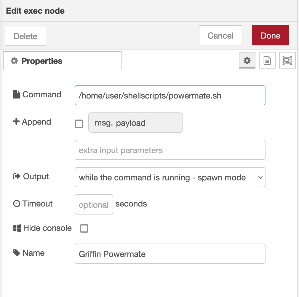
The Griffin Powermate node is a simple exec node that runs the script we created above.
M0AWS Powermate exec node
Configure the node as shown above and connect it to the inject node that’s used as a trigger. Note: Change “user” in the Command field shown above to that of your username on your Linux PC)
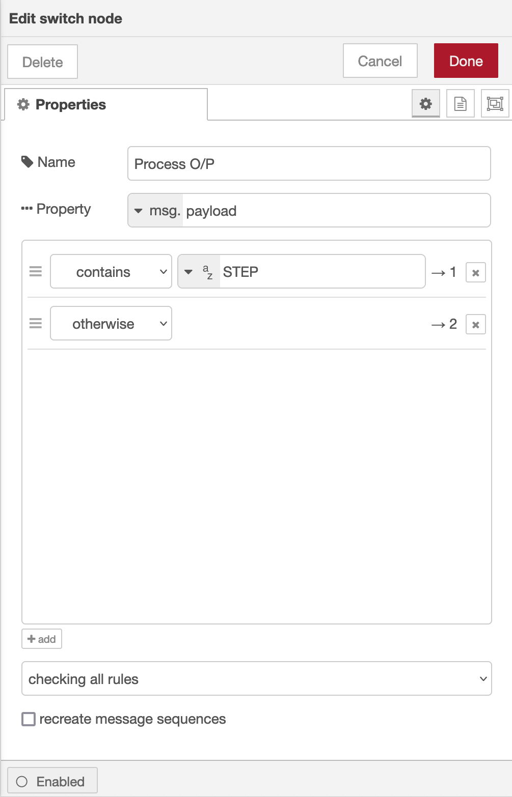
Once done create the third node in the flow, a simple switch node and configure as shown below.
Switch Node for Powermate
The switch node has two outputs, the top one is a text output that is fed into a text field to show the current step size of the Powermate device and the lower output is the numeric output that must be fed into your VFO control flow so that the VFO value is incremented/decremented by the amount output by the Powermate device.
I’ve found the Griffin Technology Powermate USB device works extremely well with Node Red and GQRX that I use for controlling the FCD SDR radio and it’s now part of my QO-100 ground station build.
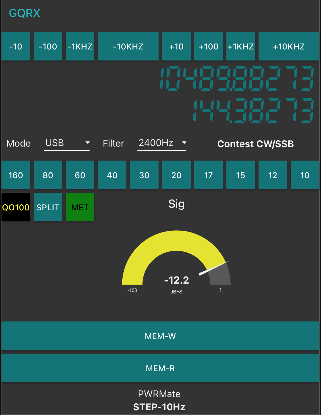
M0AWS QO-100 Dashboard with Powermate Step Display at bottom
As shown above you can see the Powermate Step size at the bottom of the dashboard, this text changes each time the Powermate device is depressed and will set a step size of 1Hz, 10Hz, 100Hz, 1Khz, 10Khz in a round-robin fashion.
The next stage of the build is the 2.4Ghz transmit path. I now have all the necessary hardware and so this part of the build can finally commence.
I’ve been chatting a lot recently on Matrix about antennas for the amateur satellites.
Since I’m currently working on building a ground station for the QO-100 satellite a group of satellite enthusiasts having been talking about the other satellites that are in orbit around this little planet of ours.
The ISS FM voice repeater on 145.990Mhz is very popular and is one of the easiest satellite stations to get into apparently. Many are using Eggbeater antennas to get an all round radiation pattern.
I’ve never looked into building or modelling such antennas and so I decided to have a go at modelling one and use it as an opportunity to see how it works.
All the modelling has been done with the antenna at 5m above ground level.
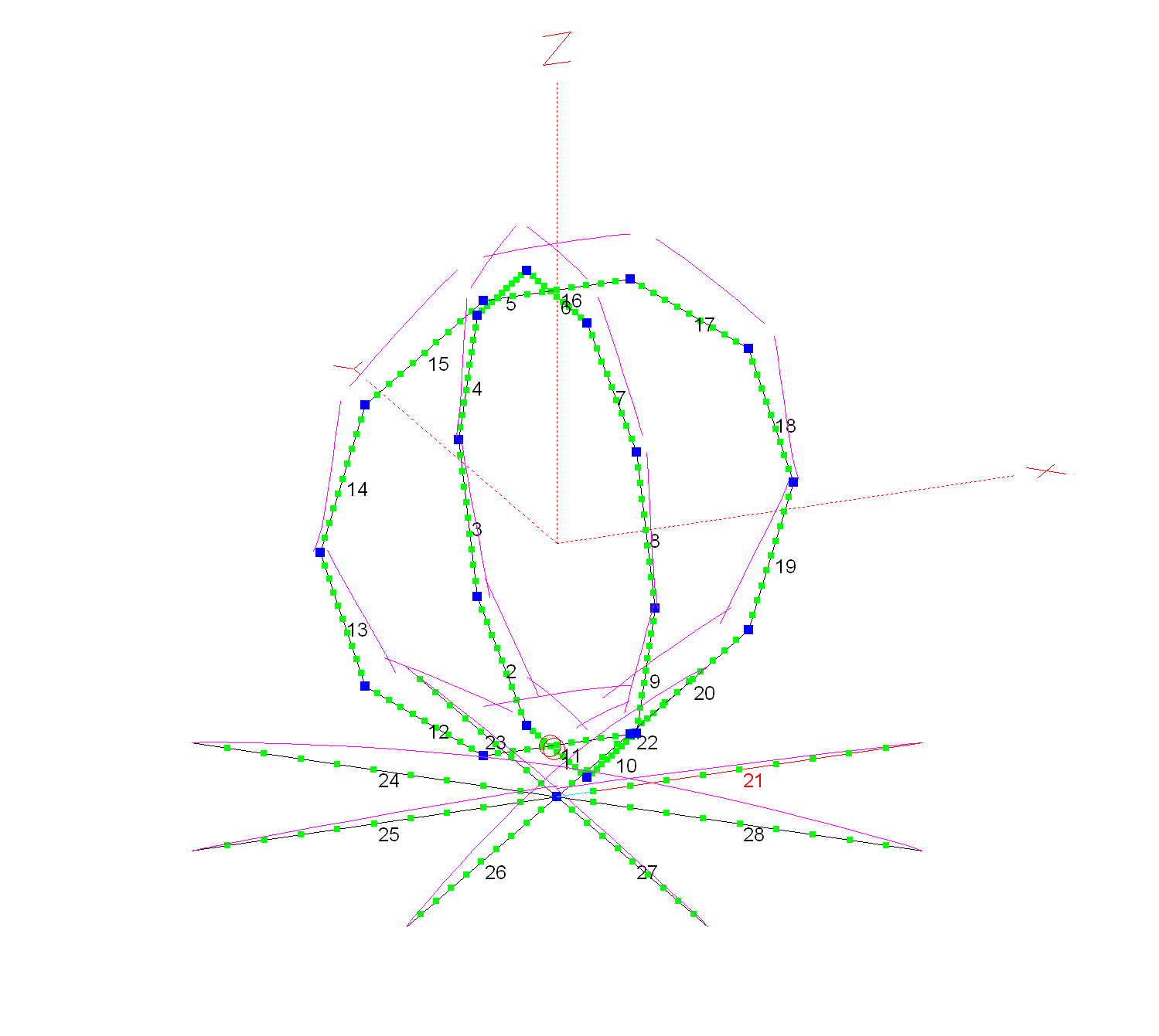
2m Band Eggbeater satellite Antenna with 8 Radials
Each loop has a circumference of 2.17m and each of the 8 radials is 0.5425m long and 5cm below the eggbeater elements. I’ve modelled the antenna using 5mm diameter conductors as this should make them resistant to wind etc. I am planning on using 5mm copper tubing for the build.
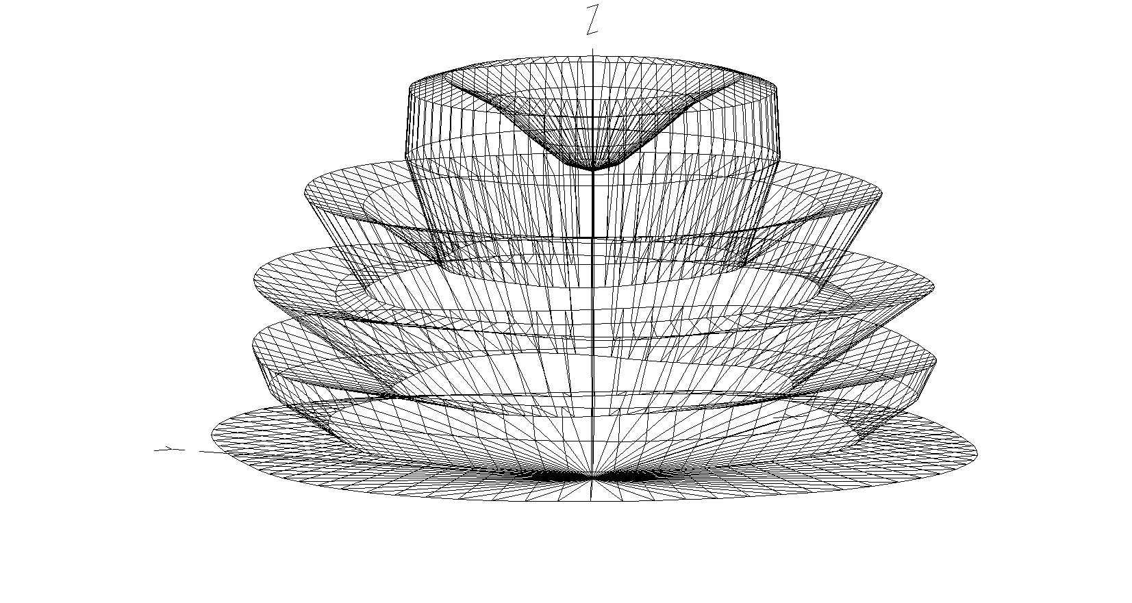
2m Band Eggbeater Satellite Antenna 3D Far Field Plot
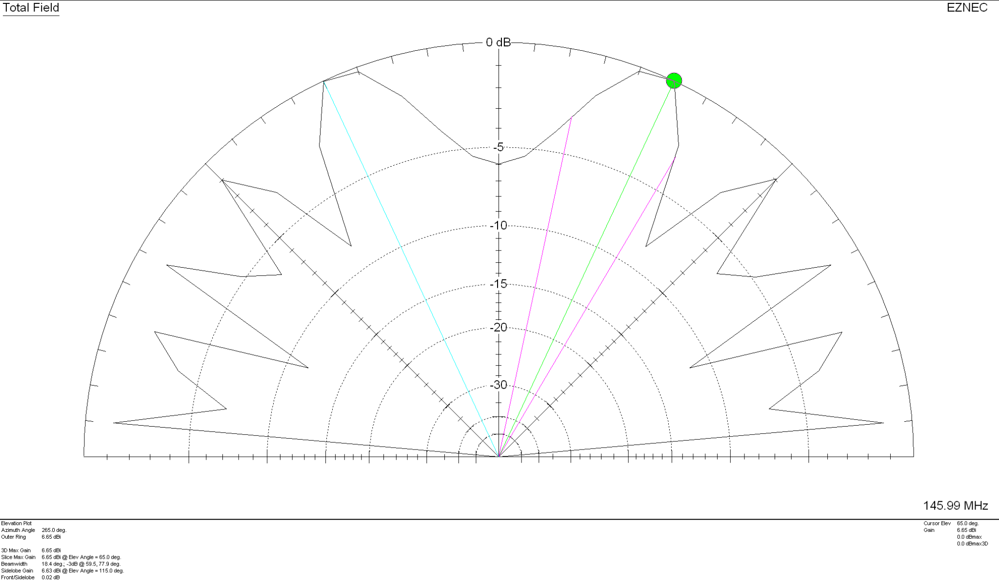
The 3D far field plot shows a typical radiation pattern for such an antenna with a very good low angle gain for working satellites on the horizon and multiple high gain lobes as the radiation angle increases. At 5 degrees the RF is horizontally polarised, ideal for shooting directly out at the horizon. This is mainly due to the phasing of the two elements. At the higher angles the RF is vertically polarised thus giving the ability to receive both horizontal, vertical and some circular radiation at a good range of angles. There is however, a very slight null directly above the antenna and so signals to satellites directly above will be attenuated slightly compared to the other two high angle high gain lobes. This will also be the case on receive.
2m Band Eggbeater Satellite Antenna 2D Far Field Elevation Plot
With 5.42dBi gain at 5 Deg this antenna has a real good shot at the horizon with the maximum gain of 6.65dBi being at the much higher angle of 65 Deg. Overall this antenna should work well for all satellites from the horizon up to almost directly above the antenna.
2m Band Eggbeater satellite Antenna SWR Curve
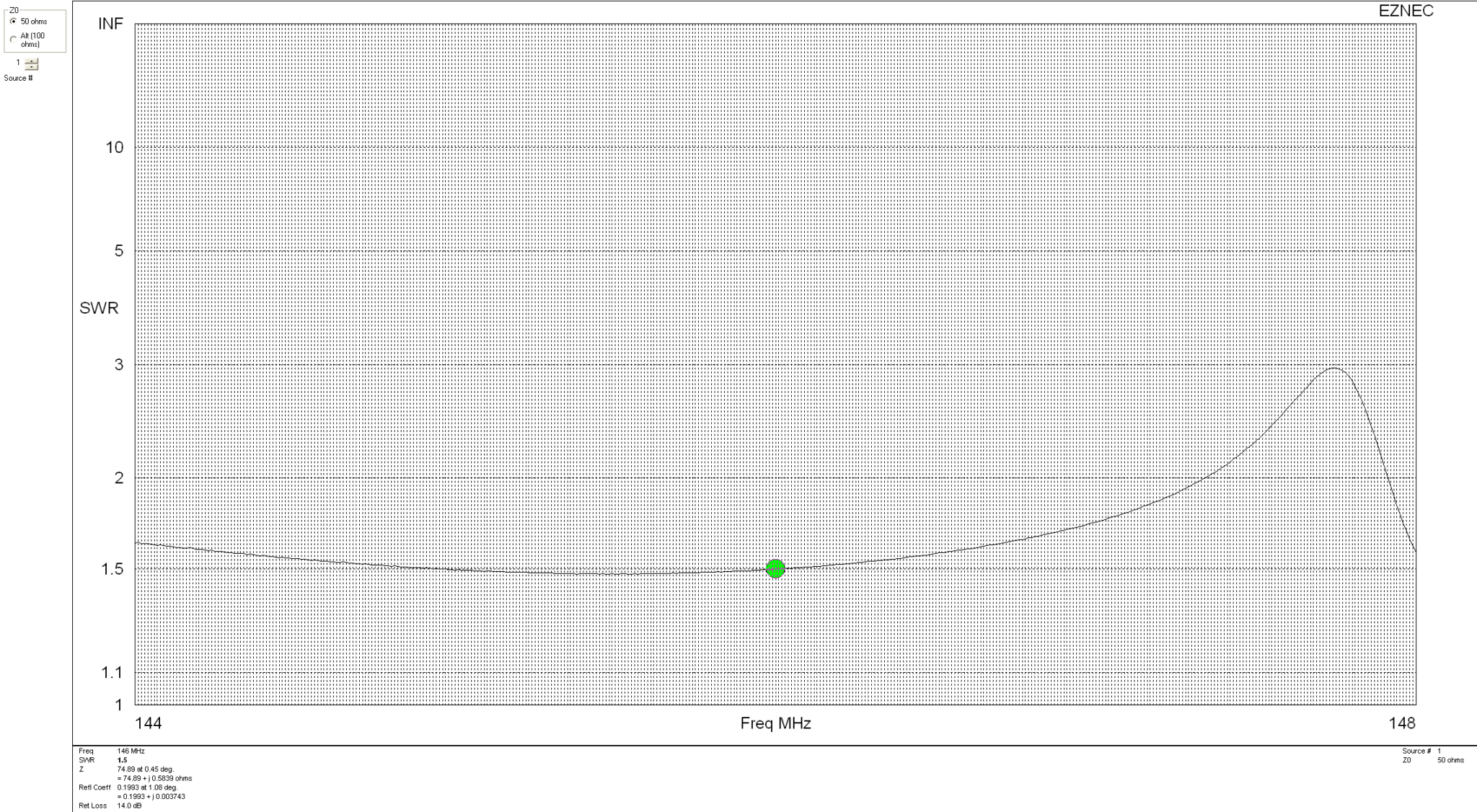
With an SWR of 1.5:1 across most of the 2m band this antenna will match perfectly to 50 Ohm coax feed. It’s really important to remember that when building this antenna the loops must be fed with a phase angle difference of exactly 90 degrees. If this isn’t accurate then the radiation pattern is affected quite drastically and spoils the overall performance of the antenna.
Details on how to create the 90 Degree phase shift between the two elements using 2 pieces of 50 Ohm coax can be found in the excellent article by ON6WG.
Since purchasing my Icom IC-705 radio I’ve only used it on the HF bands. Since the IC-705 is a “shack-in-a-box” I thought it was about time I ventured up onto the VHF/UHF bands and add another string to my bow.
Since I don’t have an antenna for these two bands I’d need to build something. I’m not really interested in DXing on the VHF/UHF bands as I’d need a yagi or two, a rotator and would need to get the entire setup up high on the chimney on the house.
We’re very fortunate in that there are a good many repeaters on VHF/UHF in East Anglia with quite a few being well within range of my QTH.
So I decided to go with a simple vertical antenna of some sort that I could easily attach to the top of a 10m spider pole and pop up in the garden without too much hassle.
The simplest of all antennas to build for any band is an end fed vertical dipole. It’s made purely from a piece of coax cable, you can’t get much simpler.
Using some dimensions I found online I unrolled a length of RG58U and set about cutting it to resonance for the two bands.
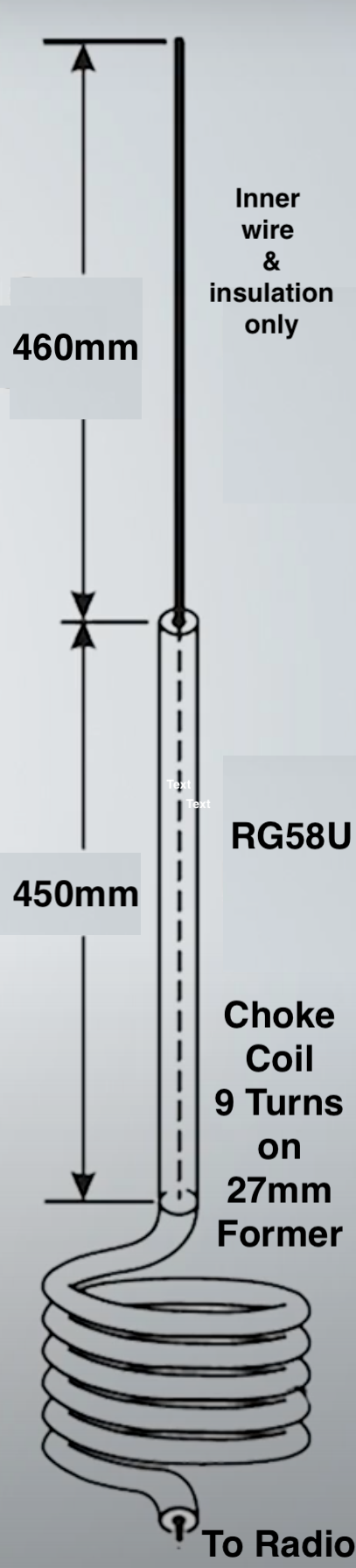
To start I measured out 910mm of RG58U and put a piece of tape around the cable at the 910mm point. I then stripped the top 460mm of the outer and braid from the coax so that the inner wire and plastic insulation was exposed. This then left 450mm of coax with the braid still in place to make up the 2nd half of the vertical dipole.
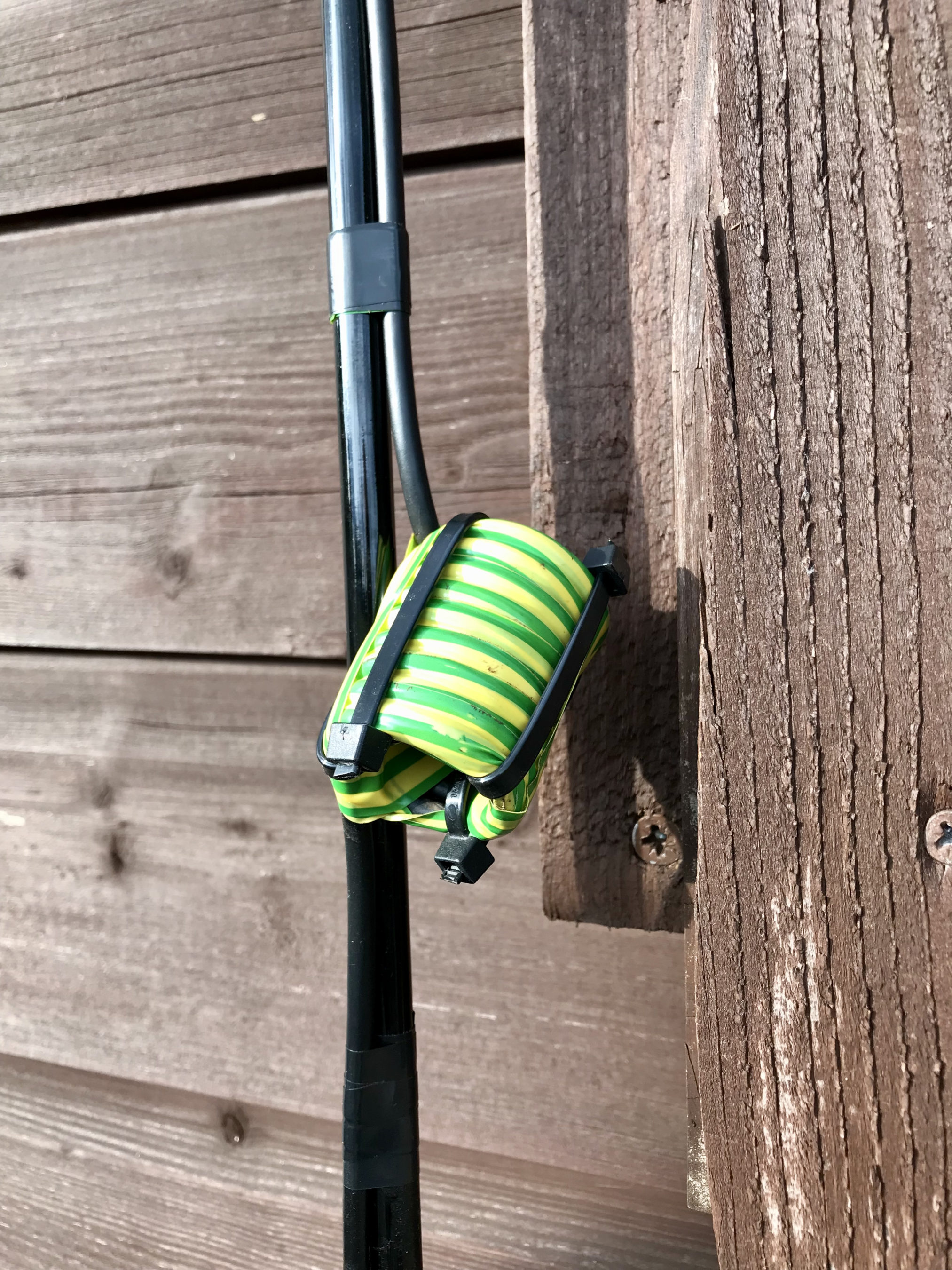
At the 910mm marker I wound the coax 9 times around a 27mm former to create a choke balun. I taped the coil up to ensure it kept it’s shape, removed it from the former and then used a few zip ties to hold it in place.
VHF/UHF End Fed Vertical Dipole Diagram
The diagram above aids in visualisation of the make up of the antenna that is made from a single piece of RG58U coax cable.
Choke Balun made from 9 turns of RG58U on a 27mm former
I next wound some electrical tape around the point on the antenna where the outer insulation and braid ended so that it would stop moisture getting into the rest of the coax and causing problems in the future. I also put a bit of electrical tape across the top of the end of the wire to stop moisture getting into the inner wire and then a piece of electrical tape around the wire to ensure it was fully sealed.
Electrical tape wound around the point where the outer braid finishes
At this point the antenna was complete! It literally took a few minutes to make. I could now either cut the coax a few centimetres from the bottom of the coil and fit a PL259 or just continue the coaxial cable back into the shack and fit a PL259 on the end. I decided to go with the latter as it’s one less connection to make.
VHF/UHF End Fed Vertical Dipole taped to the top of a 10m spiderpole
Once complete, I taped the antenna to the top of a 10m spider pole and then ran the rest of the coax back into the shack and soldered on a PL259 connector.
Raising the spider pole up to its maximum length put the antenna some 10m up above the ground. Hopefully this will give me a relatively clear path to the local repeaters.
Plugging the antenna into the IC-705 and checking the SWR I found it was <1.2:1 across the entire 2m band and <1.5:1 across most of the 70cm band. It was perfect for what I wanted!
VHF/UHF End Fed Vertical Dipole up 10m on a Spiderpole
I configured the local repeaters into the the IC-705 memories so that I could easily switch from one repeater to the next with all the appropriate tone and duplex frequency shifts set at the touch of a button.
My local 2m repeater GB3PO comes in at 5/9+10dB without any preamp and the local 70cm repeater GB3IH comes in at 5/9+5dB without any preamp. I was really pleased with the results and set about having a chat with other local HAMs on the local repeaters. It’s been a while since I’ve used the mic on this radio and it made a nice change!
To my surprise I found I could get into far more repeaters than I ever imagined. GB3NB in Norwich is 5/8 as are a number of repeaters down in Essex. This gives me quite a scope for chatting on the VHF/UHF bands via the repeater network.
To my surprise I can also hear ON0WV in Brugge Belgium, unfortunately it’s on the same frequency as the local 2m GB3PO repeater and so often gets drowned out completely but, it’s good to know that when there’s a lift in propagation I should be able to get into the near continent without too much hassle.
If you’re looking to build a simple but, effective 2m/70cm vertical for local repeater access then I highly recommend making an end fed vertical dipole. It only takes a few minutes to cut the cable to length, remove the outer sheath and braid and wind the choke balun, it really couldn’t be any easier.
For the last 24hrs I’ve had the RaspberryPi2 transmitting WSPR on 20m and 10m connected to my EFHW Vertical antenna. So far not a single spot on the 10m band, I’m assuming the band hasn’t opened in the UK over the test period.
WSPR 20m band reports over the last 24hrs
Results on 20m continue to impress with reports from the USA, West Africa coast and as far east as Georgia.
I’ll check the signal on 10m later today using my IC705 to ensure it is transmitting ok and then will leave it running for another 24hrs to see what happens.
UPDATE:
It appears there’s been a reliable opening on both 10m and 20m to the Canary Islands just off the west coast of Africa so far today.
Having just completed building my new radio shack I thought what better way to break it in than to do an all night radio session chasing the DX.
All nighters aren’t anything new for me, I did many an all night session low band DXing when we lived in France (F5VKM). Back then I had a massive cellar, part of which was a very well fitted out radio shack. With some very large antennas in our field out back I was truly spoilt with some great times on the 160m band in the dark winter months.
Now back in the UK and only just getting back into the hobby after a long break things are somewhat different. I now only have a typical small UK garden and only vertical antennas. Better than no antennas though!
The new radio shack is small compared to my super spacious setup in France but, it’s perfectly formed with all facilities.
For my over night radio session I decided to use my trusty Yaesu FTDX10, it has the best receiver I’ve ever used and is built to withstand the long haul operation.
Antenna wise I decided to use my 30m band EFHW vertical that can be tuned on most bands from 80m and upwards. I use a CG3000 remote auto tuner to match this antenna to the 50 ohm coax feed and it does a great job.
Being comfortably setup in the shack I tuned up on the 30m band and had a listen to see what shape the band was in.
Stations heard on 30m 10/11-07-22
Using FT8 I worked a bunch of European, Russian/Asiatic Russian stations with ease, the band was in fairly good shape albeit localised around Europe and Russia. Wanting to work stations a little further afield I decided to move up on to the higher bands. 12m is a band I really like but, always seem to miss when it’s open.
Tuning up on the 12m band using the same vertical that I was just using on the 30m band the FT8 section was packed with signals. At last, I’ve tuned up on the band when it’s open!
I suddenly noticed Bobby, VP8ADR down in the Falkland Islands in the WSJTX waterfall and gave him a call. He had a fair few people calling him and so I joined the list. In no time at all Bobby answered my call and we exchange SNR reports of -8dB both ways. This was surprising as later on one of the FT8 Facebook groups Bobby stated he was using 200w into a Hexbeam during our QSO, I was only using a measly 18w into my Vertical, I would had expected a much lower SNR report. Clearly Bobby’s setup was doing all the work!
Right after the QSO with Bobby I immediately went on to work PY7ZC, LU8YD, PY2ATI, LW6EQC, PY2EBD and PY2THO all in quick succession. With the Falklands, Brazil and Argentina in the log so soon it was looking like it was going to be a fun packed night.
Next up on the waterfall was 9Y4DG in Trinidad and Tobago and 8P6ET in Barbados, two really nice locations to get into the log and new ones on 12m for me.
Having worked all the DX I could hear on 12m and not wanting to just spend hours working endless European stations I tuned down onto the 17m band using the same vertical antenna. This antenna really does work well on bands it’s not designed for.
First 3 stations in the log on 17m were all from Japan, JR3NZC, JQ6RUP and JA5BDZ. With all 3 stations being well on the way to 6000 miles away this was a good start. The propagation strangely swung to the west and I got YV5DRN from Venezuela in the log.
Not seeing any other stations that I wanted to work I retuned back onto 30m again and found it was open to South America and the Caribbean.
In no time at all I had YV4CLF in Venezuela, HK2AQ in Colombia, NP4TX and NP3XF in Puerto Rico and PY7ZC in Brazil all in the log.
Being in complete darkness I decided to tune down on to the 60m band, one of my favourites, to see if there was much going on. Sure enough there were a few stations active on the limited space available.
First station worked was a new one for me FP/KV1J on St. Pierre and Miquelon Island just off the coast of New Foundland. I have to admit I had no idea where this little island was and confess to having to look it up on google maps.
I then went on to work a few East Coast USA stations all with good SNR reports for this time of year.
Stations heard on the 60m band 11-07-22
Having worked all the notable DX on 60m I tuned back onto the 17m which was now wide open to the world.
I stayed on this band for the rest of the night well into the morning grey line and beyond working some great DX including some new ones for me.
I worked many East Coast USA stations but, stations of note were 6Y5HN in Jamaica and AK6R, K6EU and K6EI in California on the West Coast USA. It’s rare for me to get into the West Coast USA for some reason.
UA0SDX in Irkutsk Siberia was also a nice one to get in the log. This is a town I was going to be riding my motorcycle through on my Mongolian trip before COVID19 and the war in Ukraine broke out and stopped the trip from happening.
It was good to get an Ozzy call in the log too, VK6EI on the West Coast of Australia came in at a strong -15dB SNR giving me a surprising -14dB SNR report, incredible considering I was using just 22w into my vertical antenna.
Well after sunrise the DX was still pouring in and I worked KL7TC in Fairbanks Alaska, a new one for me that made me very happy as I’d been trying to get into Alaska for some time but, never seemed to time it right. Today was my day!
Another station I was really pleased to get into the log was V31MA. I’ve tried to get a QSO with this station many times but, have never succeeded until today. I called for about 20mins and eventually got a reply putting a huge smile on my face. -16dB SNR sent and -19dB SNR received, I was happy that I finally have Belize in the log.
The last station worked was RA0FF way over on the far East Coast of Russia, the complete opposite direction to Belize. Located in Yu-Sakhalinsk right on the Russian coast opposite Japan and at 5270 miles, this is my longest distance Russian station worked so far and one I was very happy to have in the log. I always get good take off towards Russia whether it be directly east or over the North Pole to the far eastern parts of the Siberian wilderness.
I had a great night chasing the DX on the HF bands and being retired didn’t have to worry about going to work after such a long night. I highly recommend that you try an all nighter at least once in your HAM radio career, you get the opportunity to work stations that you’d normally not hear during the day time hours.
You can see the full list of stations worked on the over nighter on my WSJTX Log page.
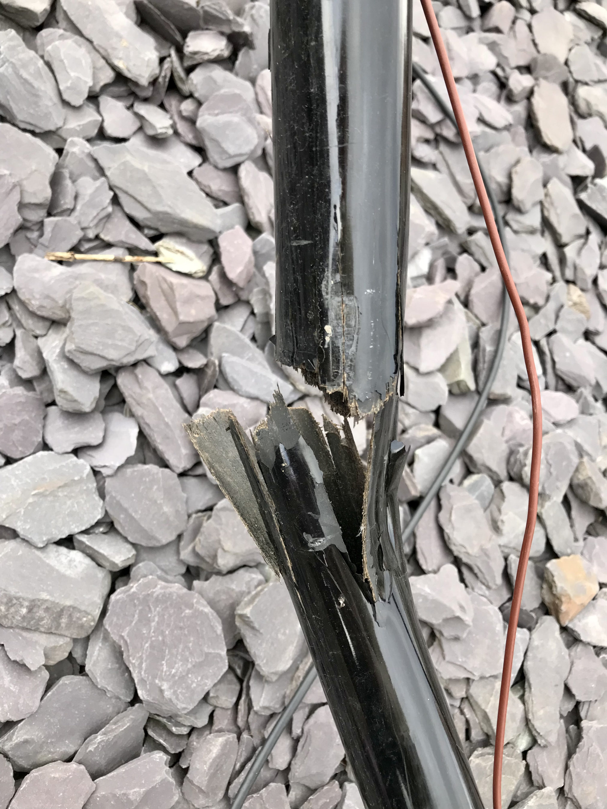
A few days ago we had a bit of a storm come through which brought down one of my extending fibreglass poles. Sadly I wasn’t home to be able to go out into the garden and take it down and hence I now have a badly broken pole.
It’s quite an old pole and has given me sterling service and so I can’t really complain. This has however, brought forward my decision to get something a little sturdier to hold up my wire creations.
Going online I finally ordered what I’ve really wanted for some time, a Spiderbeam Spiderpole 12m HD extending fibreglass pole. These poles really are much stronger than the cheap, thin walled fibreglass poles I’ve been using and so, should handle the wind somewhat better.
This will also allow me to get a longer wire into the air as it’s some 3m longer than the poles I’ve been using to date.
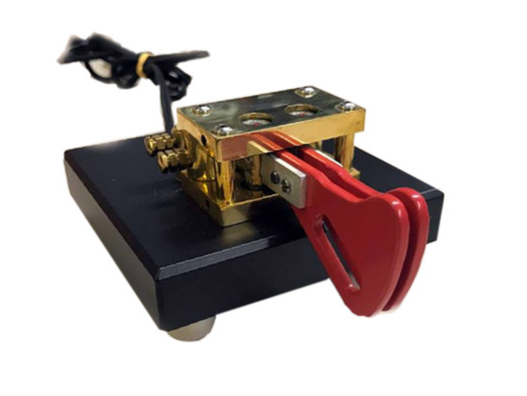
I also decided to order a new morse twin paddle key today too. I’ve been looking for some time but, couldn’t decide which key to purchase.
I finally decided to go with the Vine Twin Paddle RST-TP1 key. It’s quite a heavy lump so shouldn’t wander around the table during use. I’m looking forward to receiving it!
To recap, the NVIS antenna is a 30m long end-fed wire that is between 3 and 4m above the ground over it’s entire length. This is the longest wire I could get into my tiny U.K. garden and so I wanted to see what was really possible with such a low short wire on the low bands. My goal was to get good Inter-G signals so that I could chat with other U.K. and close European stations during the summer months. The tuning is done automatically by the CG3000 remote ATU I picked up very cheaply on Ebay.
Having very anti-antenna neighbours I have to tread carefully not to upset them as I have already rattled some cages having the 20m EFHW Vertical on an extending fibre glass pole at the end of the garden overlooking the farmers field.
The CG3000 remote ATU matches the 30m wire nicely on the 160m band with an SWR of less than 1.2:1 across the entire band with multiple retunes. It’s certainly very convenient to have such a setup.
Setting the power output on the radio to 25w which is the maximum I use for FT4/FT8 on the Yaesu FTDX10 I started WSJT-X and waited to see what I could hear. With the background noise swinging between S7-9 most of the time I was surprised at how many stations were being decoded. Some of the stations were barely visible on the waterfall but, I got consistent reliable decodes.
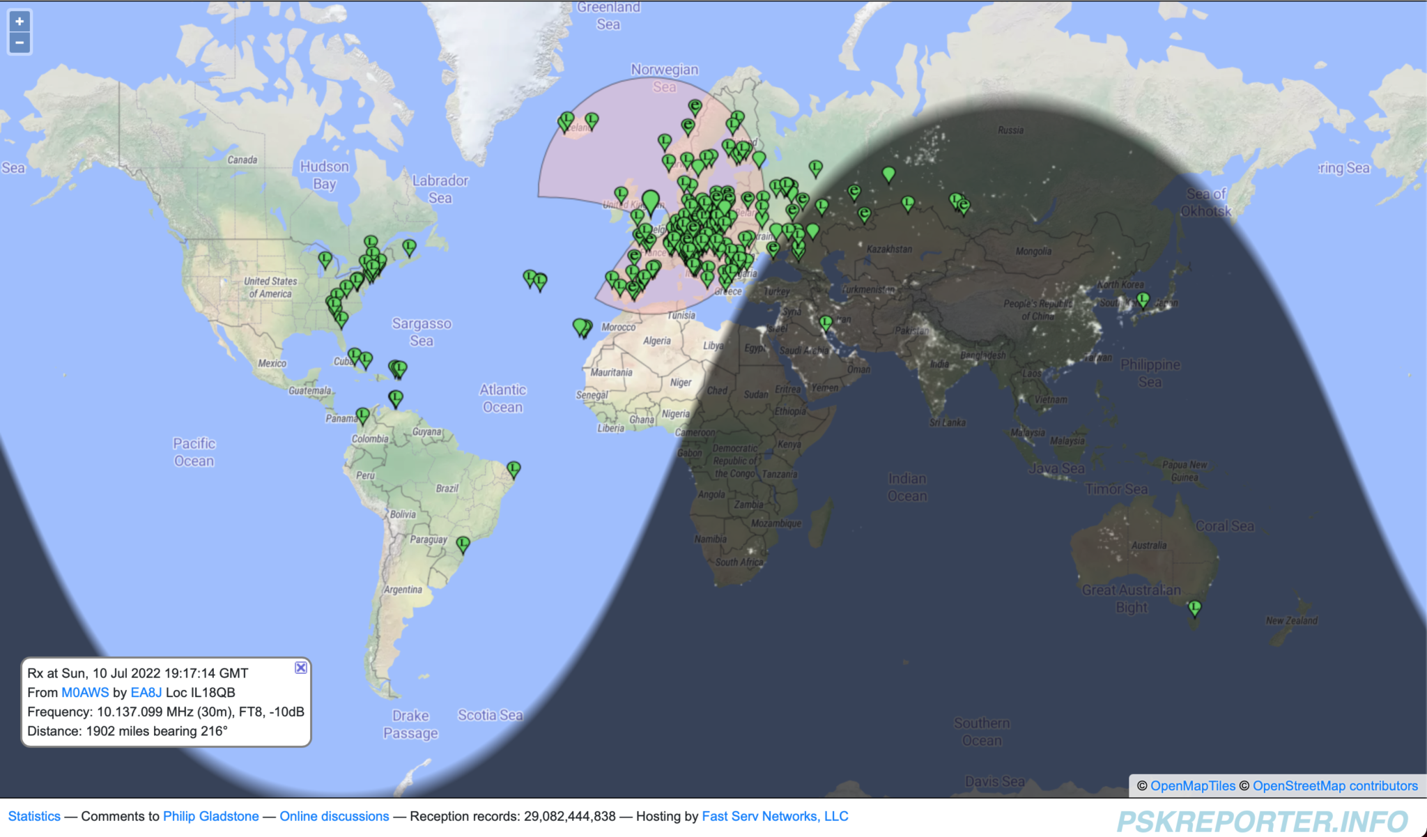
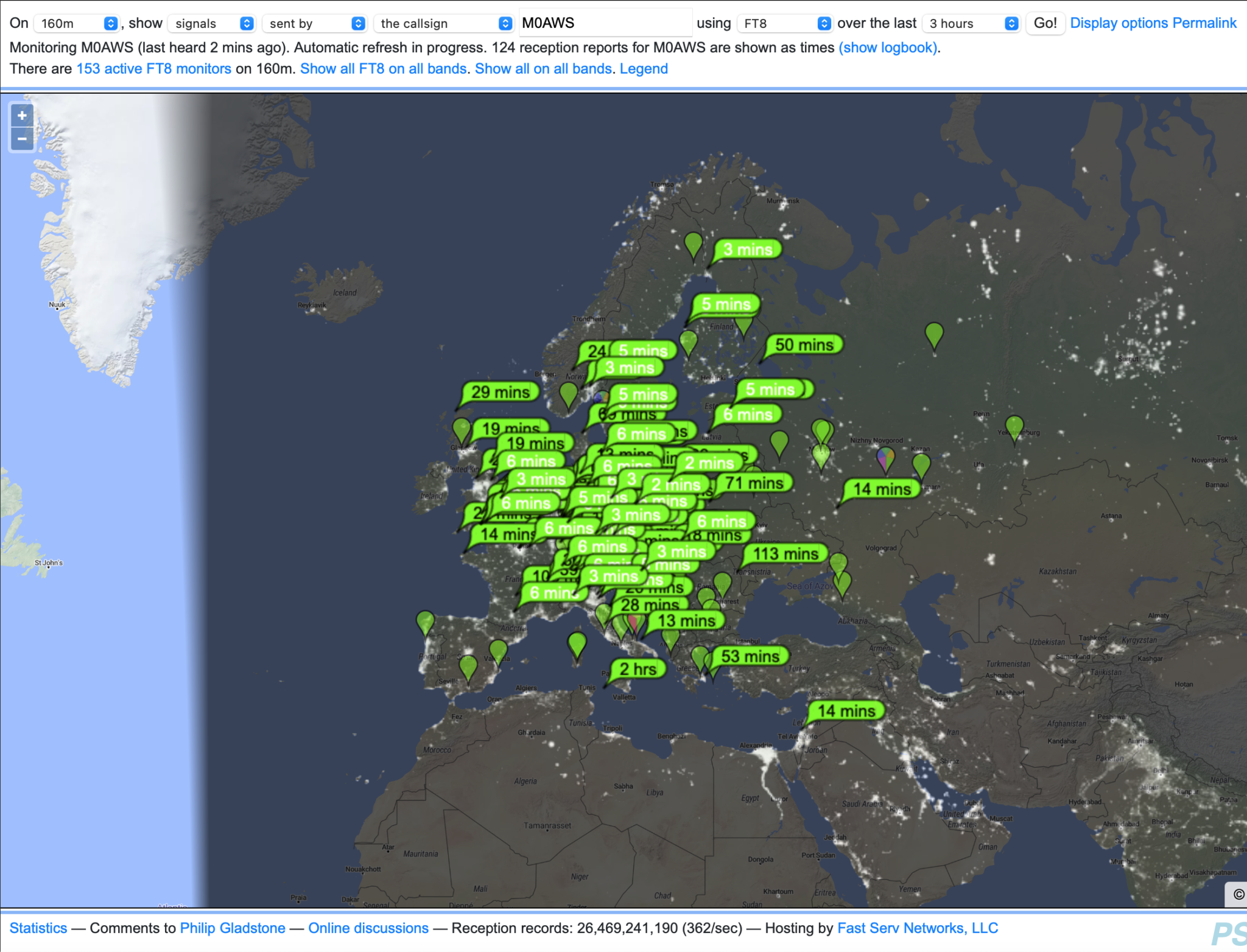
Stations heard during a 1 hour period on 160m NVIS Antenna Experiment
As you can see on the map above I was hearing stations from all over Europe and well into Russia. There certainly isn’t the proliferation of stations on the 160m band that there are on the 40m band but, there were enough for me to get some good results.
It was nice to reliably copy some U.K. stations on 160m FT8 even though I didn’t hear a single SSB station on the band.
Map showing stations that heard M0AWS on 160m during the NVIS Antenna Experiment
Over a period of about 3.5 hours I was heard by a good number of European stations but, wasn’t able to work all that I heard as I was struggling to compete with the much more powerful stations. Limiting my transmit power to 25w to protect the PA on the radio does tend to limit my success at getting through to stations at times but, I am a firm believer in being able to hear better than I can shout, especially on the low bands.
Map showing all stations worked during the 160m NVIS Antenna Experiment
Over the test period I didn’t work a huge number of stations but, I did manage to work stations over a large area of Europe with the best distance being 1004 Miles into Finland, much further than I ever thought would be possible with such a simple setup.
I’m sure that when the band is in better shape with lower noise levels and better propagation the antenna will post probably perform better but, it’s certainly proved it can do the short hop NVIS comms that I was looking for.
I have designed a new NVIS antenna for the garden which manages to incorporate considerably more wire into the same space that is resonant on the 80m band. With the CG3000 remote ATU it should tune up well on 40m-160m and give much better results. This design does require a 10m fibre glass expending pole which I need to purchase before I can erect it in the garden. I’ll get all the information for the design onto the Antenna section of the website soon.
So to summarise, a 30m end-fed wire at between 3 and 4m above the ground will give good NVIS results on 40m-160m with a very low visual impact. For those like me that have a small garden, a simple antenna like this is much better than no antenna at all.
Since setting up the new station at my U.K. QTH I’ve not had any Inter-G contacts. This has mainly been due to the fact that the antennas I’ve currently got in place are all designed for chasing DX and so have far too low a radiation angle to be able to talk to other U.K. stations.
One of the things I do like about radio is the local chatter on the low bands. In the summer months working Inter-G on the low bands is most enjoyable so, I decided to put up a simple Near Vertical Incident Skywave (NVIS) antenna ready for the summer.
Unlike my French QTH, here in Suffolk we only have a tiny garden and so it’s a challenge to get any length of wire up that is anywhere near long enough for the low bands.
A quick measuring of the garden I worked out I could get 30m of wire approximately 3-4m off the ground at best. I’m very aware of my anti-antenna neighbours and so it needs to be as stealthy as possible.
I decided to use some 1.5mm wire that I had in the workshop and utilise the high washing line poles that are already in place to get the wire along the max length of the garden.
With the wire in place and connected to the CG3000 auto remote tuner that I got off of Ebay for a song, ground post and radials connected I found that the antenna tunes up fine on all 3 low bands, perfect!
Tuning up on the 40m band I had an SWR 1:1 anywhere on the band. I could hear a number of strong U.K. stations and a few Dutch and German stations too. Since I’m on the East Coast of the U.K. The Netherlands and Germany aren’t that far away as the crow flies.
Setting the radio onto 40w SSB (First time on SSB in a very long time!) I put out a call. First station to come back was G8VVY, Robin in Malmesbury Wiltshire. Signals weren’t particularly strong and I gave him a 4/4 report and got a 5/5 in return.
Next station was PA3GLK, Dave in The Netherlands. Again signal reports were 5/5 and 5/6 but, perfectly readable.
Next up was G0SXC, Kevin in Lancashire. Signal reports were 5/9 both ways this time, very strong and fully quietening, the high angle radiation was doing its thing!
Last call was ON3PAT, Pat in Belgium. Very strong signals both ways, 5/9++ at a distance of 153 miles. NVIS propagation is working very well. I turned the output down to just 25w and Pat still gave me a 5/9 report.
Later in the day I decided to run some FT8 QSOs on 40m to see how far I could get reliably with no more than 25w. I was hoping that I may just be able to get 1000 miles as an absolute maximum but, be able to work stations at 100 Miles or less with ease.
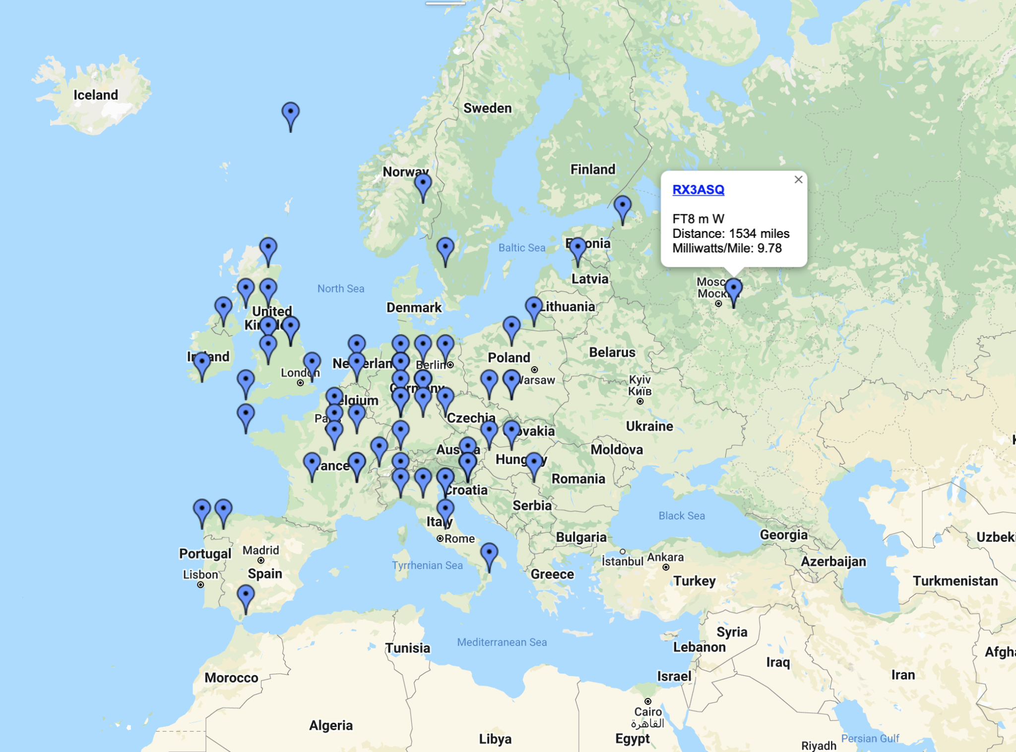
Map showing NVIS FT8 contacts on the 40m band
As you can see on the map above, 1534 miles was the best achieved, RX3ASQ just east of Moscow. The thing that pleased me most was the number of U.K. stations I could hear with the closest being just 43 miles away. Most European stations were easily worked even with reduced levels of power (10w) and so I’m hoping that this simple end fed NVIS antenna will become my goto antenna for local chatter on the 40m band.
What was very interesting was what I could hear on the antenna, I didn’t expect to hear any DX stations at all however, I was surprised to see stations from Mongolia, Japan and the USA popping up in the WSJT-X window.
Obviously I couldn’t get back to them as my angle of radiation was far too high to get a signal out over those distances but, it just goes to show what can be a heard on a very low long wire.
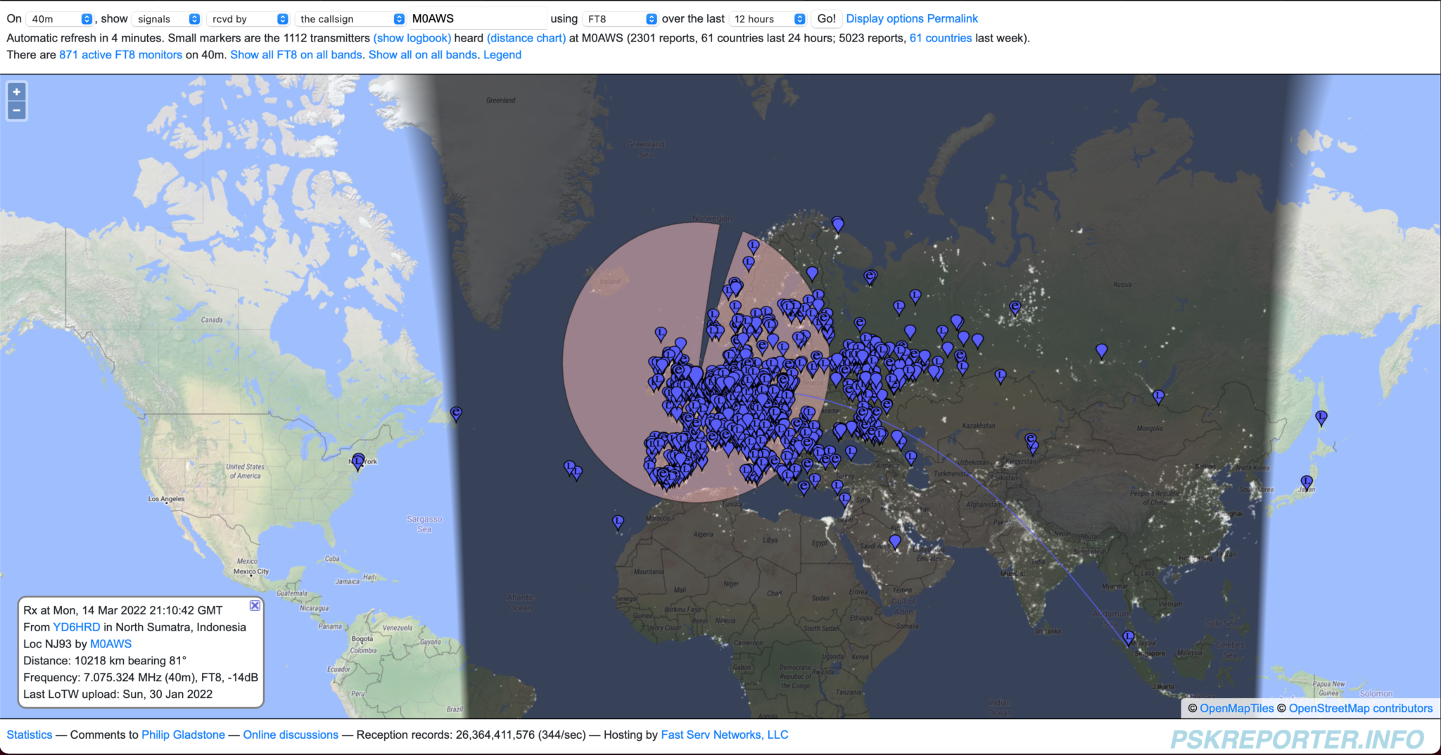
Map showing stations heard on 40m using NVIS antenna
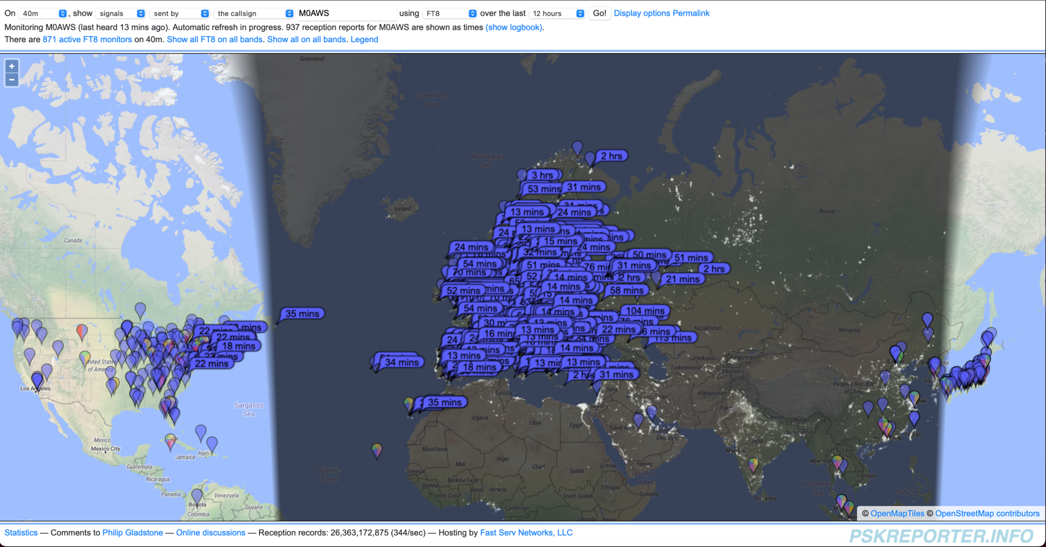
By the end of the evening to my surprise I had been heard in the USA, I was amazed to see where I’d managed to get into with such a low antenna. The main cluster of stations were in the U.K. and Europe of course which is exactly what I wanted from this antenna.
Stations that heard M0AWS on 40m FT8 using NVIS antenna
So the next test will be on the 80m band, I’m hoping to get similar results on SSB with inter-G stations being easy to work. I doubt I will be able to get anywhere near the 1500 miles I achieved on the 40m band but, I’ll be more than happy with U.K. and EU stations.
More soon …
We use cookies to ensure that we give you the best experience on our website. If you continue to use this site we will assume that you are happy with it.