20m EFHW Vertical + 49:1 Unun = DX

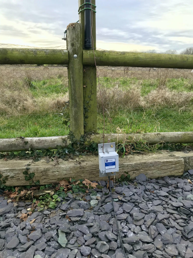
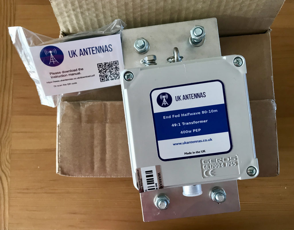
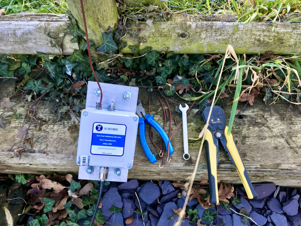
My 49:1 Unun arrived from UK Antennas today, lost no time getting it into the garden and connected to the 20m EFHW Vertical antenna.

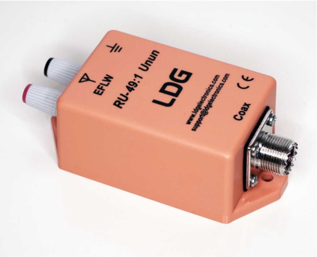
49:1 Unun from UK Antennas

I’m really pleased with the 49:1 Unun, really nicely put together and packaged professionally, great to get such a nice British made product!

Connecting the Unun up to the antenna I found that it added a little extra inductance I hadn’t planned for and so I needed to shorten the vertical wire a little to compensate.

Tuning the 20m EFHW Vertical

It took 3 snips of wire to get the antenna resonant in the 20m band again, with an SWR of 1.3:1 and the sun starting to set I decided that was fine for now and I’ll fine tune it tomorrow in the daylight. (See end of article for update)

Heading into the shack the 20m band was buzzing, lots of big signals and DX. I switched on to the 10m band and checked the SWR there, 1:1 across most of the band, perfect!

I then went on to check the 15m band, now I wasn’t expecting a match as it shouldn’t resonate there but, I found a 2:1 SWR across the band, weird!

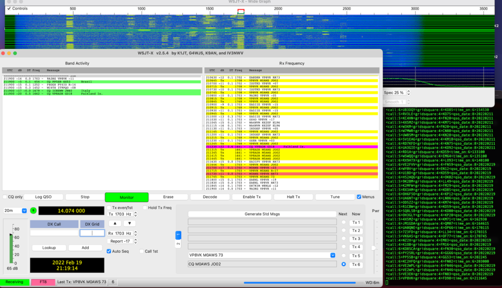
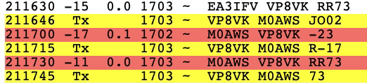
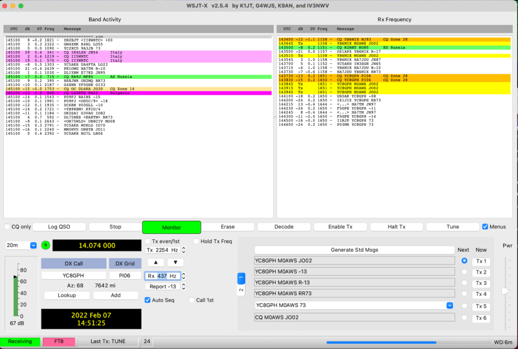
So back on 20m, I plugged in the MacBook Pro and started WSJT-X in FT8 mode to see what was around.

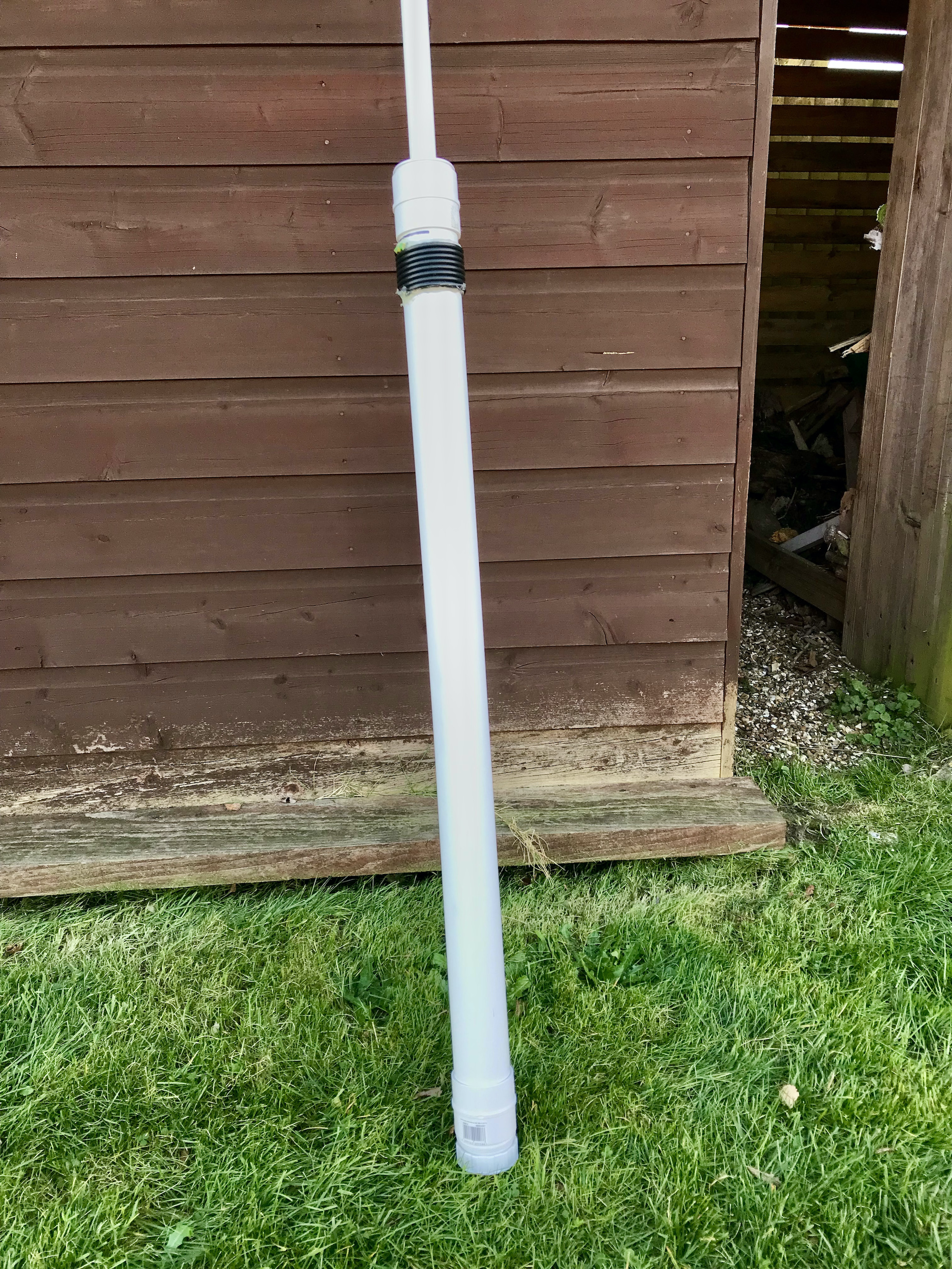
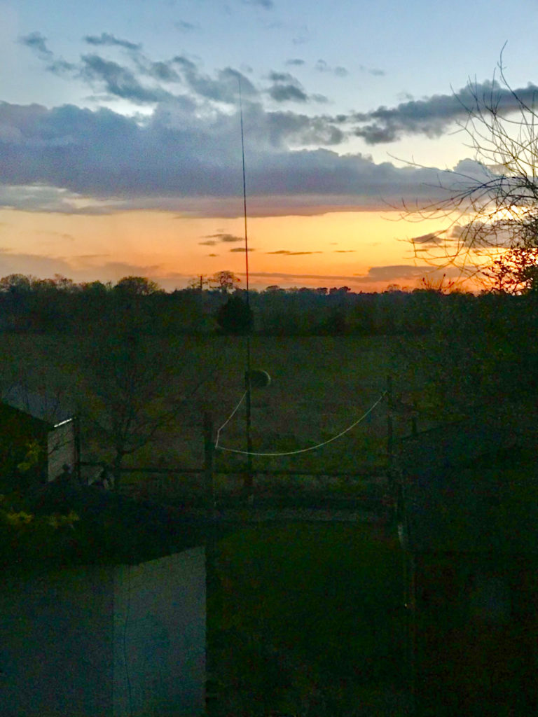
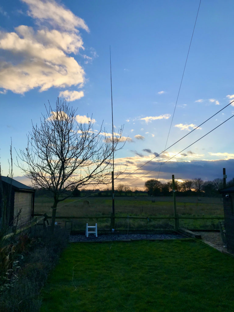
20m EFHW Vertical at the end of the garden

First contact was into Canada, VE2FVV with a -10 report both ways and 2962 miles, not bad for 20w.

I then worked a flurry of stations from the USA but, the one I was really pleased with was PP1WW in Brazil. 5610 Miles using just 20w, this EFHW vertical really does has a lovely low angle of radiation.

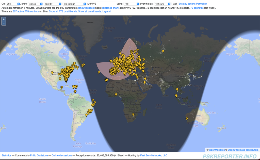
PP1WW was the last station worked as it was dark by this time and the band closed. It was interesting to watch the PSKReporter site to see where I was being heard.

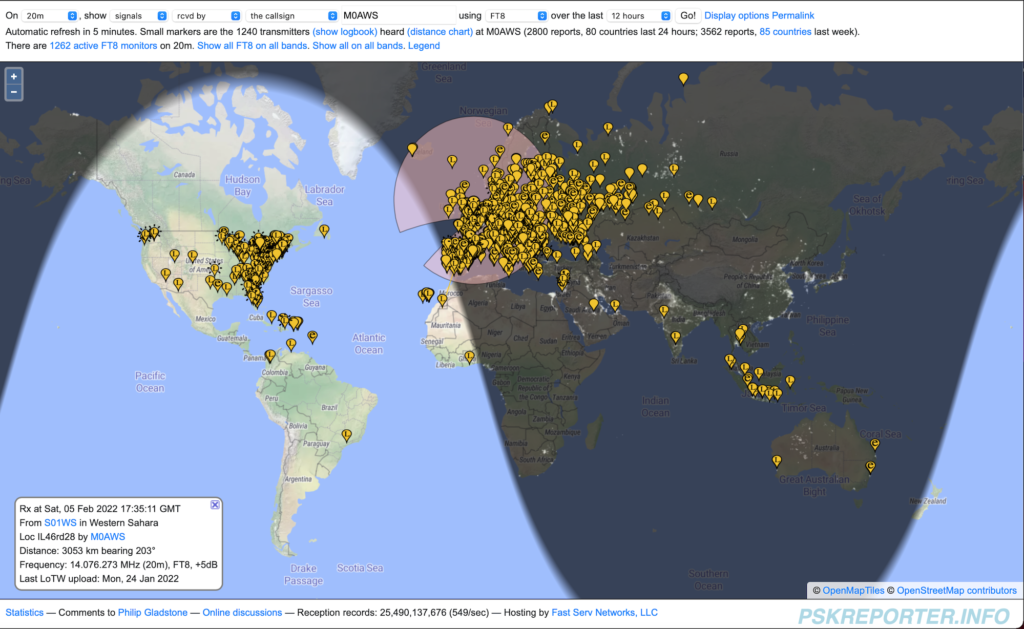
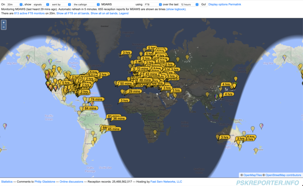
Stations that heard M0AWs on 20m

As you can see from the PSKReporter screenshot above, I was heard pretty much all over the world. I saw a number of VK stations in Australia pop up on FT8 but, never managed to get an answer back from any of them even though they reported hearing me on the PSKReporter site.

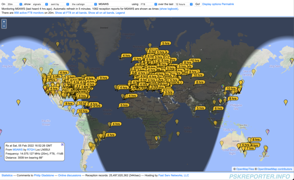
I was also pleased with the number of stations that I heard, once again good global coverage.

Stations heard by M0AWS on 20m

Band conditions are generally poor at the moment and we’re in a bad part of the 11 year sunspot cycle. Hopefully in the coming years propagation will improve and we’ll be able to work the world on just a couple of milliwatts!

I also tuned up onto the 10m band and heard quite a few FT8 stations on there, I was surprised as I wasn’t expecting the band to be open.

So tomorrow, I need to fine tune the antenna for the 20m band and get the SWR down to 1:1, hopefully this won’t affect the 10m band tuning too much.

Once the 12m Spiderpoles are back in stock I’ll get one ordered and build the 40m EFHW Inverted L that I’ve designed, I’m hoping it will open up the 40m/20/15/10m bands for some DXing over the summer months.

UPDATE: I ended up snipping off a total of 34.5cm of wire to get the SWR 1:1 at 14.100Mhz. This makes the entire 20m band useable with the SWR less than 1.5:1 at each end of the band. 2nd contact after trimming the wire was VK2LAW at 10454 Miles using just 25w of power.

Information as to why it’s best to keep the feed point at ground level for this antenna is here.

More soon …

adi2html v0.5 release

Following on from my original article where I detailed the adi2html Bash script that reads in the WSJT-X log and creates an HTML version of the data so that it can be presented in a palatable format on websites (See my WSJT-X log here), I’ve now released v0.5 for public consumption.

In adi2html v0.5 I’ve added colour to the webpage that is generated to make it easier on the eyes and rewritten the function process_log() so that it uses the column name to identify each field instead of the row position.

By making this change it should cope just fine if the order of the fields is ever altered in the WSJT-X log during its development.

As before the code can be downloaded using the link below.

If you use my code please consider leaving the footer in place so I get some credit, thanks!

Free Great Circle Azimuthal Map

I don’t know about you but, when I’m in the garden erecting antennas I find it hard to work out which way I need to orient the antennas to get the DX I want to work. This is especially true with Delta Loop directional antennas.

I remembered that when I lived in France I had a lovely Great Circle Azimuthal Map on the wall in the radio shack showing the world as viewed from space directly above my QTH in Brittany, this would be ideal for my U.K. QTH too.

Hunting on the internet I soon found the site where I got it from, N6NT has a wonderful little website full of handy little widgets, one of which is the Great Circle Azimuthal Map Generator.

M0AWS Great Circle Map

The map is generated in PDF format and can be downloaded and printed locally.

I hope this snippet of info will be of use to some of my readers, it’s certainly very handy for me!

More soon …

Going up in Frequency!

Ever since I got my Class A HAM Radio licence I’ve always been fascinated by the low bands.

160m, 80m and 40m have been my favourite go to bands for chasing DX for many years and I’ve really enjoyed overcoming the challenges that come with such low frequency radio operations. Working DX on 160m I learnt a lot, having a good receiver and a quiet antenna are far more important than having a lot of power. The QRM/QRN on top band often masks the weak DX signals and so designing and building antennas that have a relatively low angle of radiation but, are super quiet on receive is a skill that all top band DXers should embrace.

It’s particularly hard to work DX on 160m in the summer months however, all those DX signals are still there, they’re just masked by the static crashes that plague top band throughout the warmer months.

Discovering the grey line was a real eye opener too. Getting up early in the morning to catch that magic moment that starts just before the sun rises to about an hour afterwards, with DX signals pouring in from VK/ZL before the D layer gets established again. Discovering that on the grey line signals from afar often arrive from a very high angle and can be heard much better on a large horizontal loop near the ground than a large vertical.

As you can tell, I’m passionate about the low bands but, now I’m back in the U.K. and have a U.K. sized garden again those days of large full wave antennas on the low bands are gone and so I must look to pastures new.

To this end I’m going to get onto the higher frequency bands, 20m and upwards. I must admit that I’ve hardly used these bands as I’ve always been so focused on the lower bands.

Currently I have delta loop for 30m up in the garden, this is a great band for us CW and digital guys, it’s a band I really enjoy and so will continue to use it whilst discovering the higher bands.

So I thought I’d start with the 20m band, it’s a band that I’ve heard is really easy to work DX on. Being much quieter than the low bands I’ll give the delta loop antennas a rest and venture into the land of vertical antennas again.

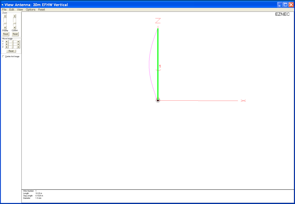
Doing some antenna modelling on EzNEC the End Fed Half Wave (EFHW) antenna has a great radiation pattern with a nice low angle of radiation and even some gain compared to a dipole.

Construction will be easy as the antenna is so small compared to the low band antennas I’ve built in the past.

20m Band EFHW Vertical Antenna

An EFHW antenna is a relatively simple affair and for 20m it’ll be somewhere around 10.25m tall depending on where on the band I resonate it.

The difficult thing about half wave or any multiple of half wave antenna is that they present a very high impedance at the feed point. Unlike a half wave dipole that is made up of two quarter wave legs that present an almost perfect match to 50 Ohm coax cable (or a 1:1 balun), the EFHW will have a much higher impedance, normally in the range of 2000 Ohms or more. Having such a high impedance also means high voltages at the ends, something to be very aware of especially if you have children or pets in the garden!

Matching to this type of antenna can be done two ways, a simple LC circuit for high impedance feed points or via a 49:1 Unun.

Since I’ve built 1:1 baluns in the past for my delta loop antennas I’ve decided to go the way of the 49:1 Unun.

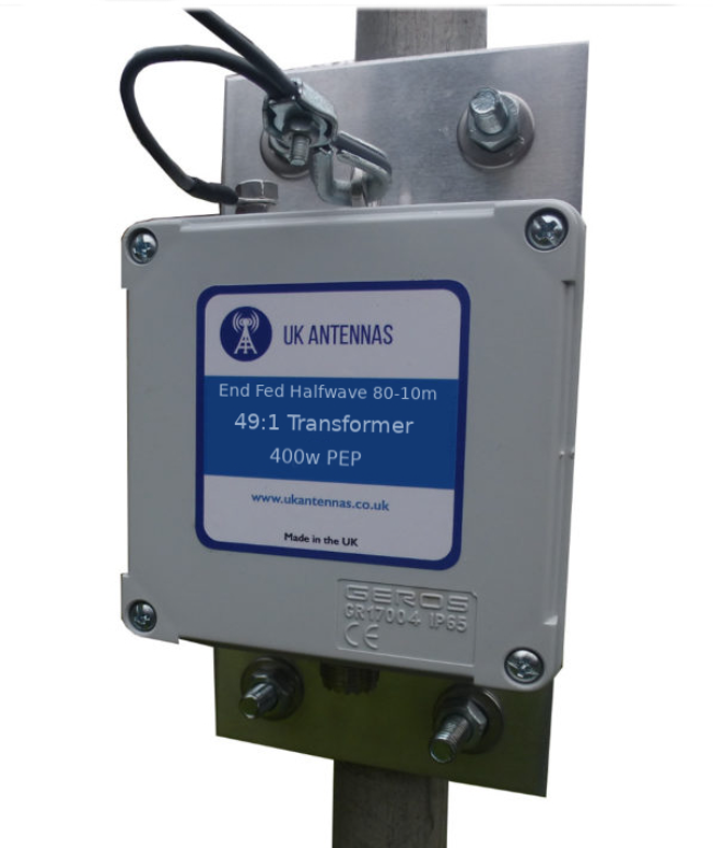
Looking online for parts to build a 49:1 Unun I stumbled across UK Antennas, they seem to have a wide selection of pre-built EFHW solutions and some very nice looking 49:1 Ununs capable of handling 400w, much more than I will ever throw at it. Contacting Ian the owner of the company via Ebay I found he has a 49:1 Unun in stock that he can ship to me next day so I decided to go ahead and order one rather than source the parts and build it myself.

UK Antennas 49:1 Unun

With the Unun sorted, let’s take a look at the radiation pattern for an EFHW Vertical on the 20m band.

Since I’m looking to do mainly CW and digital modes I’ll be tuning it for the lower end of the band.

Modelling this on EzNEC I’m pleasantly surprised at the radiation pattern of such a simple vertical.

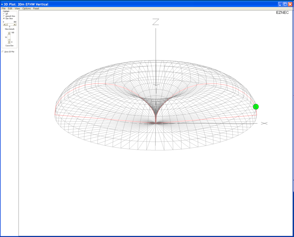
20m EFHW Vertical 3D Field Plot

To get a radiation pattern like this on the low bands requires a very large vertical, on 160m we’re talking 80m in height!

On 20m an EFHW is only around 10.25m long, very easy to put up in most U.K. sized gardens using nothing more than an extendable fibre glass pole. The 3D Field Plot shows the lovely deep null in the centre as you’d expect and a great low angle circular radiation pattern.

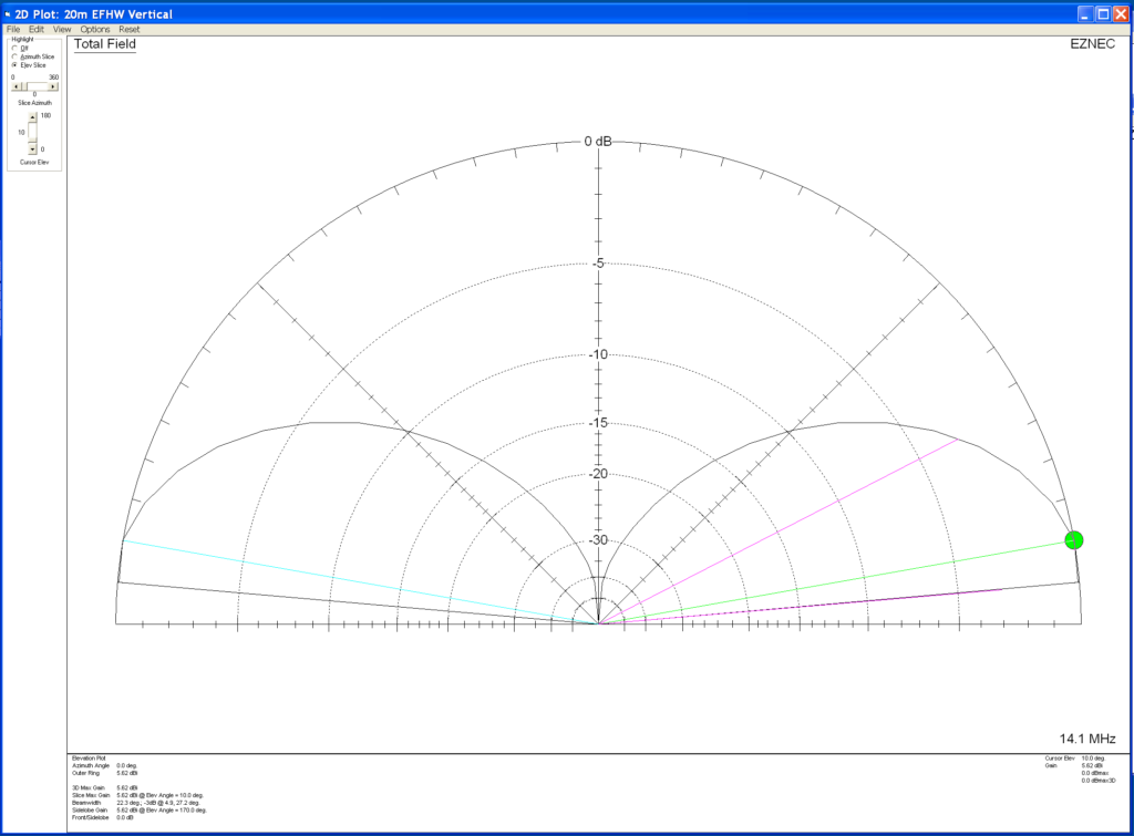
20m EFHW 2D Field Plot

The elevation 2D field plot really shows the beauty of this antenna.

5.62dBi at 10 Deg and 5.56dBi at 5 Deg, perfect for the long haul DX chaser. The wide deep null in the centre will help attenuate the signals arriving at high angles from the EU that plague us on the East Coast of the UK.

So, it’s time to go find some wire, get cutting and get a fibre glass extendable pole mounted in the garden ready for the arrival of the 49:1 Unun.

More soon ….

UPDATES:

More info on antenna performance here.

Going QRP with the 20m EFHW Vertical and IC-705

Keeping it simple but effective – 20m EFHW Vertical

adi2html v0.3 update

I spent 20min this morning updating the shell script that I wrote to read the wsjtx_log.adi file and create an HTML version of the information for my website. ( Original article here )

The code is a bit shorter now and runs quite a bit faster as I’ve altered the way some of the data is handled.

As before the code can be downloaded using the link below.

If you use my code please consider leaving the footer in place so I get some credit, thanks!

Create HTML webpage from wsjtx_log.adi file

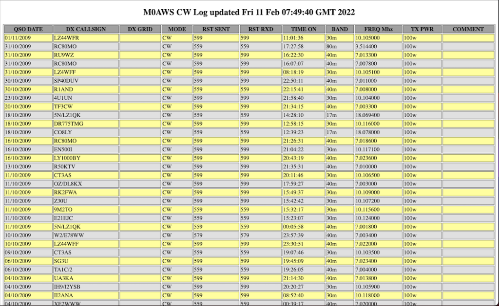
I had some spare time today so I finished a small BASH program that I started writing yesterday that reads the wsjtx_log.adi file and writes the data out in HTML format so that it can be incorporated into my website (See the Logs Menu).

(Sorry the font is so small but WordPress is crap at displaying code!)

It’s a fairly simple piece of code that anyone who is into Linux and has a basic understanding of the BASH shell will easily be able to comprehend. (Yes there’s a little awk and sed in it just to add to the entertainment value!).

There are a few places where the code can be improved which I’ll address in v0.3 when I have time but, for now I’ll put it online just incase anyone is interested in using it.

If you do use the code please consider leaving the footer in place so I get some credit.

More soon …

Fun evening on 30m FT8

I spent yesterday evening on the 30m band running WSJT-X in FT8 mode whilst getting to know the new radio. I must say I am impressed with the Yaesu FTDX10, the receiver really is extremely good at pulling out the weakest of stations.

WSJT-X in FT8 mode running on my MacBook Pro

I have a very simple setup at the moment, just the one antenna for 30m currently so I don’t have a lot of bands available. Hopefully this will change in the coming months as I work on building a new multi band antenna for the station.

I’m still getting to know WSJT-X and FT8, it’s a new mode for me and quite different to how things were 15 years ago when I was last active.

With a little perseverance I soon got the hang of it and was working stations with ease. I’m very much a wait and pounce type DXer, so my QSO turn over is low but, I get the stations I want to work rather than just a multitude of European stations who are all on my doorstep.

It was interesting to watch the band conditions change as the grey line moved across the Atlantic. One by one countries further west started popping up on the band.

30m FT8 Early Evening view

At 18:00GMT PSKReporter was showing mainly the multitude of European stations running FT8 on 30m with the Azore and Canary Islands starting to appear along with a couple of stations from the East Coast USA.

30m FT8 19:00GMT

As the grey line continued west more and more DX stations started to appear including a station in South Africa. I worked a bunch of stations in the Ukraine and Russia and then started picking off the stations in the USA one by one.

30m FT8 all stations heard (Screenshot taken next day)

By the end of the evening there were stations from South America and the Caribbean coming through. I spent over an hour trying to work CO8LY in Cuba, he was coming in at -10dB at my end but, sadly he never heard my 15w signal. I did try splitting the RX and TX frequency in WSJT-X so that my signal was to the side of the pileup but alas I never got through. Later in the evening I found CO8LY calling CQ over and over but, once again he never heard my replies. A real shame as it’s rare to hear Cuba over here on the East Coast of the U.K.

At 22:30GMT I closed the station down and headed to bed, I didn’t work a huge number of stations but, I had a lot of fun chasing the ones I wanted to get.

It’s interesting to note that the closest stations worked was 800 miles away, I think that is the first hop for my 30m Delta Loop Antenna. With the antenna being so quiet on receive and the FTDX10 having such a good receiver, it was very easy to pick out the stations 2000 miles or more away from my QTH. Most of the time I was able to exchange signal reports with stations that I called. It’s impressive to be able to exchange reports with stations that are -18dB or more below the noise level.

RUMlogNG List of stations worked on 30m FT8 mode

It was nice to get into Lebanon and Israel, two countries that have always been difficult to get into from my U.K. QTH.

A total of 20 stations worked, not a huge count but, it gave me some time to get used to the radio and it’s settings.

I also had a tune around 40m, the FT8 section was packed with stations from all over the world. I can’t wait to get onto 40m, it’s one of my favourite bands and I’m hoping to be able to work some good DX with QRP power levels.

I also listened on 80m and 160m, both were very active with mainly European stations on FT8 and SSB.

With my roll of coax arriving today I’l spend some time putting together a new coaxial run to the antenna and start working on an LC tuning unit for the new vertical I’m designing.

More soon …

Thoughts on a new antenna …

I’ve started thinking about antennas for the M0AWS QTH. Unfortunately we only have a typical U.K. sized garden now, which is tiny compared to the acres we had when we lived in France (F5VKM).

So, small gardens means small antennas.

The only direction I can go really is up, although most of my neighbours are very antenna unfriendly!

Like most radio amateurs in the U.K. I’m trying to find a single antenna that will give me the best performance possible on as many bands as possible.

Of course we all know there is no unicorn antenna that does it all but, with some compromise we can do fairly well on a mix of bands with a little consideration.

To this end I’ve been looking at Inverted L antennas. It’s not an antenna I have any real experience of but, it’s interesting to research.

40m End Fed Half Wave Inverted L

I started with a design for the 40m band. A simple end fed half wave inverted L antenna that consists of two parts. The vertical section is 11.95m high and the horizontal section is 8.7m long. Total length of wire is 20.65m. Modelling the antenna with 1.5mm wire it gives some surprising results.

3D Field Plot on 7.1Mhz
2D Field Plot on 7.1Mhz

As shown in the two field plots above, the antenna has an extremely low angle of max radiation making it ideal for DXing. Gain at 10 Deg is 3.99dBi, not to be sneezed at. The 3D plot shows the overall radiation pattern to be almost perfectly circular.

On the 20m band the antenna presents a favourable pattern considering it’s a full wave length long.

The angel of radiation is somewhat higher than on 40m but, this is to be expected.

2D Field Plot on 14.1Mhz

On the 20m Band the antenna gives a gain of 7.07dBi at 25 Deg. A higher angle of radiation than on the 40m band but, still very usable. At 5 Deg there is 4.29dBi of gain which makes it ideal for DXing.

3D Field Plot on 14.1Mhz

On the 15m band the pattern isn’t as good as on 40m & 20m however, it would still be usable.

3D Field Plot on 21.1Mhz
2D Field Plot on 21.1Mhz

With a gain of 6.04dBi at 25 Deg it should perform very well on the 15m band. At 10 Deg there is a gain of 1.12dBi. The overall pattern is a bit lopsided and it also has more high angle radiation than I really want but, like all multi band antennas there’s always a compromise.

Next I modelled the antenna on the 10m band, the 3D pattern is rather alarming but, it has potential.

3D Field Plot on 28.1Mhz

There’s a lot of high angle on the 10m band and a somewhat out of balance pattern but, there’s also gain to be had at a lower angle too.

2D Field Plot on 28.1Mhz

The main gain is 6.37dBi at 45 Deg, ideal for short hop communications however, there is 3.58dBi of gain to be had at 10 Deg, much better for DXing.

It’s not ideal for 10m by any means but, when you take into account that the antenna is 2 wave lengths long it’s hardly surprising.

I’ve still got a lot more work to do on this modelling but, it has huge potential.

I’ve not even started thinking about impedance matching yet, I know it’s going to be a monster and nowhere near 50 Ohms but, I’m sure a simple LC network will do magic with matching it to the transceiver.

More soon …

FTDX10 CAT Control Problem Solved!

Following on from my article about the issues I had with the Silicon Labs VCP/USB to Serial driver that’s required to be able to use the CAT controls on the FTDX10 via the USB connection I decided to take a different approach to the problem.

Since the driver was incompatible with something that is already installed on my MacBook Pro (Most likely Virtualbox) and rendered the computer unusable I decided to search for a USB to Serial converter that worked with Apple computers without the need for proprietary drivers.

It didn’t take long to find a suitable adapter, the Sabrent USB 2.0 to Serial (9-Pin) available on Amazon uses the FTDI chipset that is natively supported by Apple MacOS without the need for proprietary drivers to be installed. This makes it a simple plug and play adapter.

Unfortunately both the adapter and the FTDX10 have a male DB9 connector and so a female to female DB9 adapter is also required to make the connection.

Connecting the DB9 to the FTDX10, setting the RS232 port to 38400 on the radio and within the WSJT-X software I soon had control of the radio from the MacBook Pro.

To get the sound from the radio to the MacBook all I needed to do was connect the USB lead into the back of the radio and into the 2nd USB port on the MacBook. Since the sound card in the FTDX10 is supported natively by MacOS 11.6.2 (Big Sur) without the need for the Silicon Labs driver, this completed the setup.

So I now have full digital modes and rig control without installing any proprietary drivers on my MacBook Pro.

I tested the setup using FT8 on 30m this afternoon, it worked seamlessly.

Problem solved!

Silicon Labs VCP Driver for FTDX10 CAT Control Issues

To get my MacBook Pro talking to the Yaesu FTDX10 CAT controls so that I could use WSJT-X and FT8 I had to install the Silicon Labs CP210x VCP Driver so that it recognised the USB to Serial connection within the radio. This initially worked well however, over time I found my MacBook Pro started misbehaving.

Silicon Labs CP210x Macintosh OS VCP Driver v6 Release

The problem I had was that the MacBook Pro would wake from sleep but, the screen wouldn’t come on. The same issue occurred when booting the MacBook Pro from cold, the machine would boot but, the screen wouldn’t come on. Sometimes the screen would flicker during a cold boot and then eventually stay on, only to go off again permanently if the MacBook went to sleep.

I uninstalled the driver but, the problems continued. After much investigation the only thing left was to reinstall MacOS Big Sur.

Fortunately the way MacOS is configured, it’s possible to reinstall the O/S without losing any of the applications and data, a great relief for sure. I do have a Time Machine backup just incase though!

MacOS reinstalled and stability has returned once more, so it’s definitely the driver that has caused the screen problem.

So I’ve now raised a case with Silicon Labs asking for assistance resolving the issue, hopefully I’ll get a response.

I also put a message on the wsjtx.groups.io message board to see if anyone else has experienced this issue, so far no one has responded.

I’ll update the blog with any progress.

More soon …